News

Home / Author / Gao Shuying — Product After-Sales Service Specialist / 650.1731 SMA-C-JLMR240-1: Reliable SMA Connector Engineering for Flexible RF Cable

650.1731 SMA-C-JLMR240-1: Reliable SMA Connector Engineering for Flexible RF Cable


Yangzhou Jingcheng Electronics Co., Ltd. is professional in designing, developing, producing, sales and service of RF (Radio Frequency) coaxial connectors.
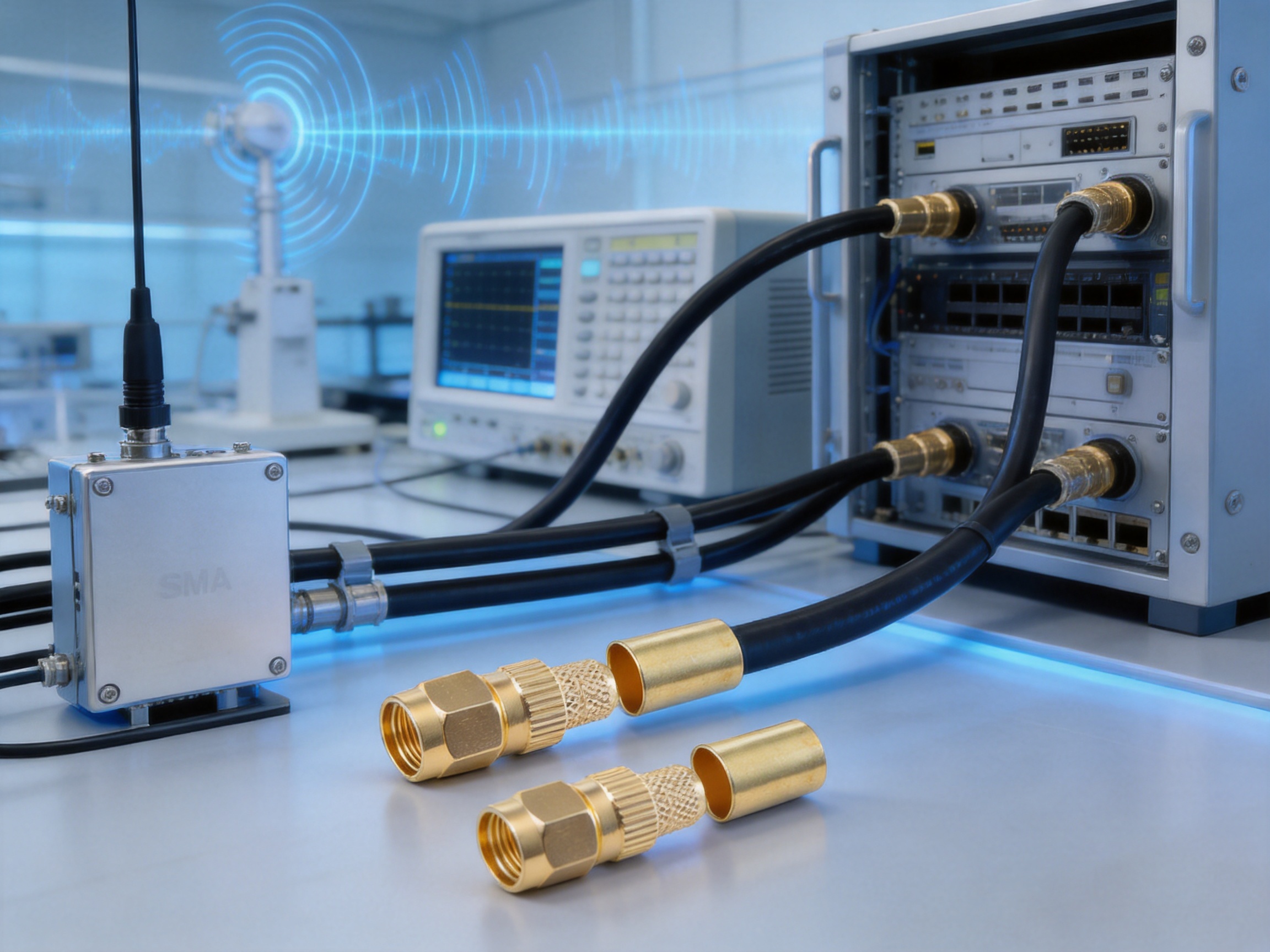

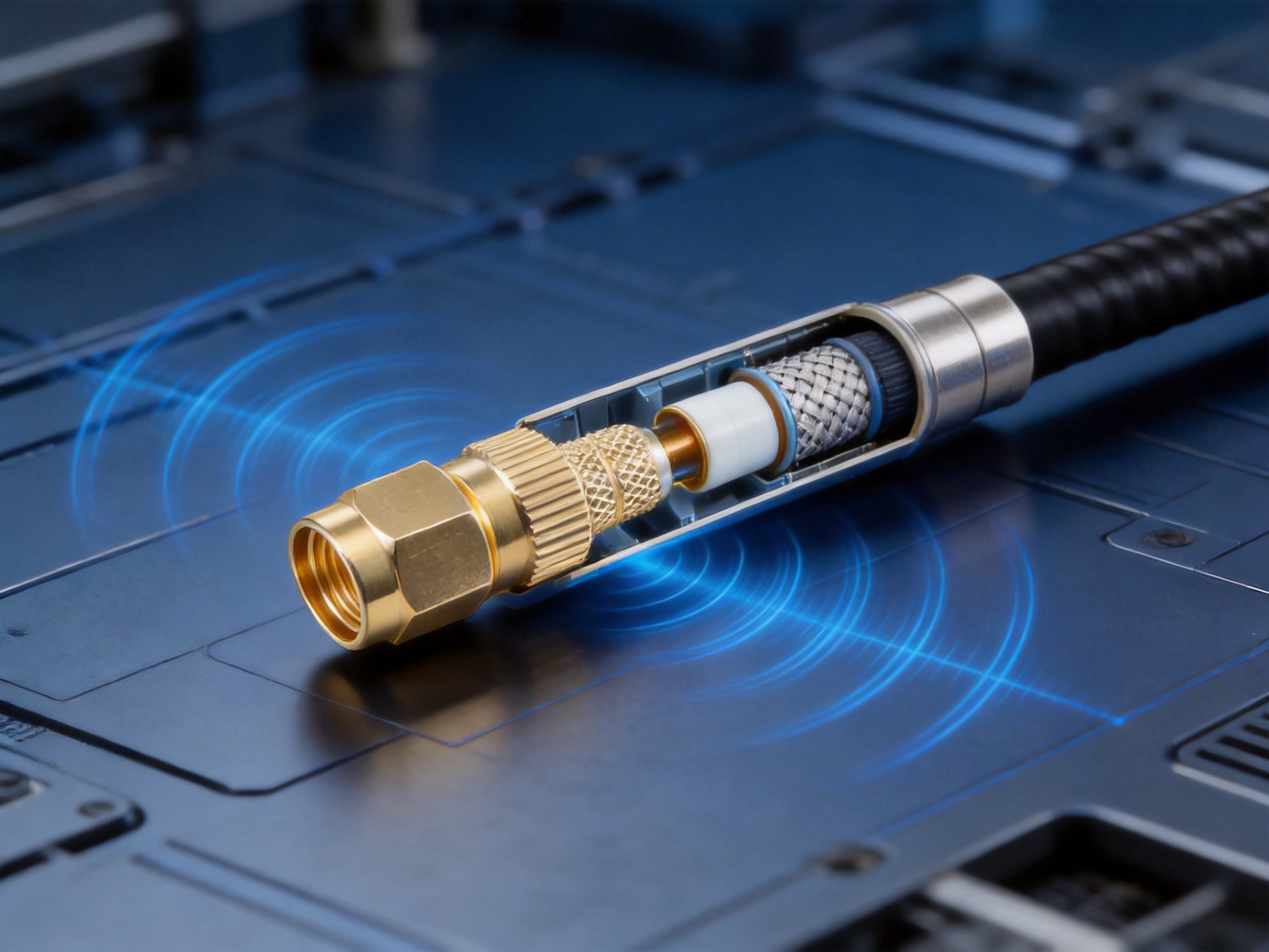
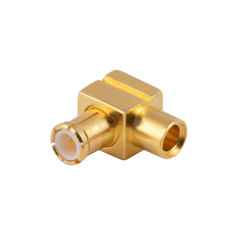
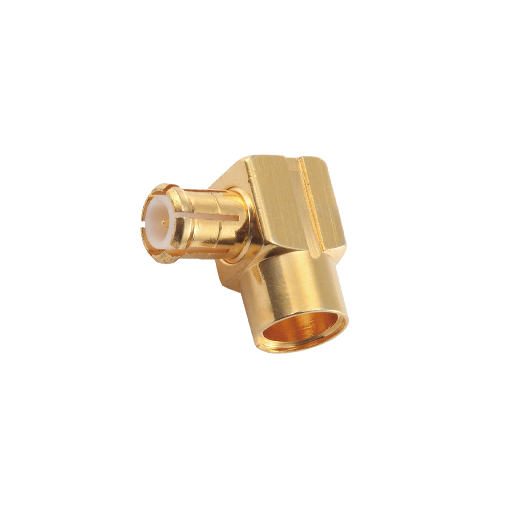
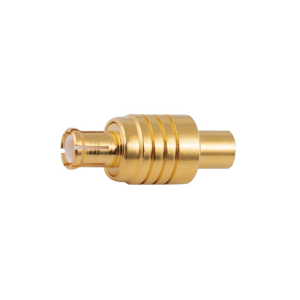
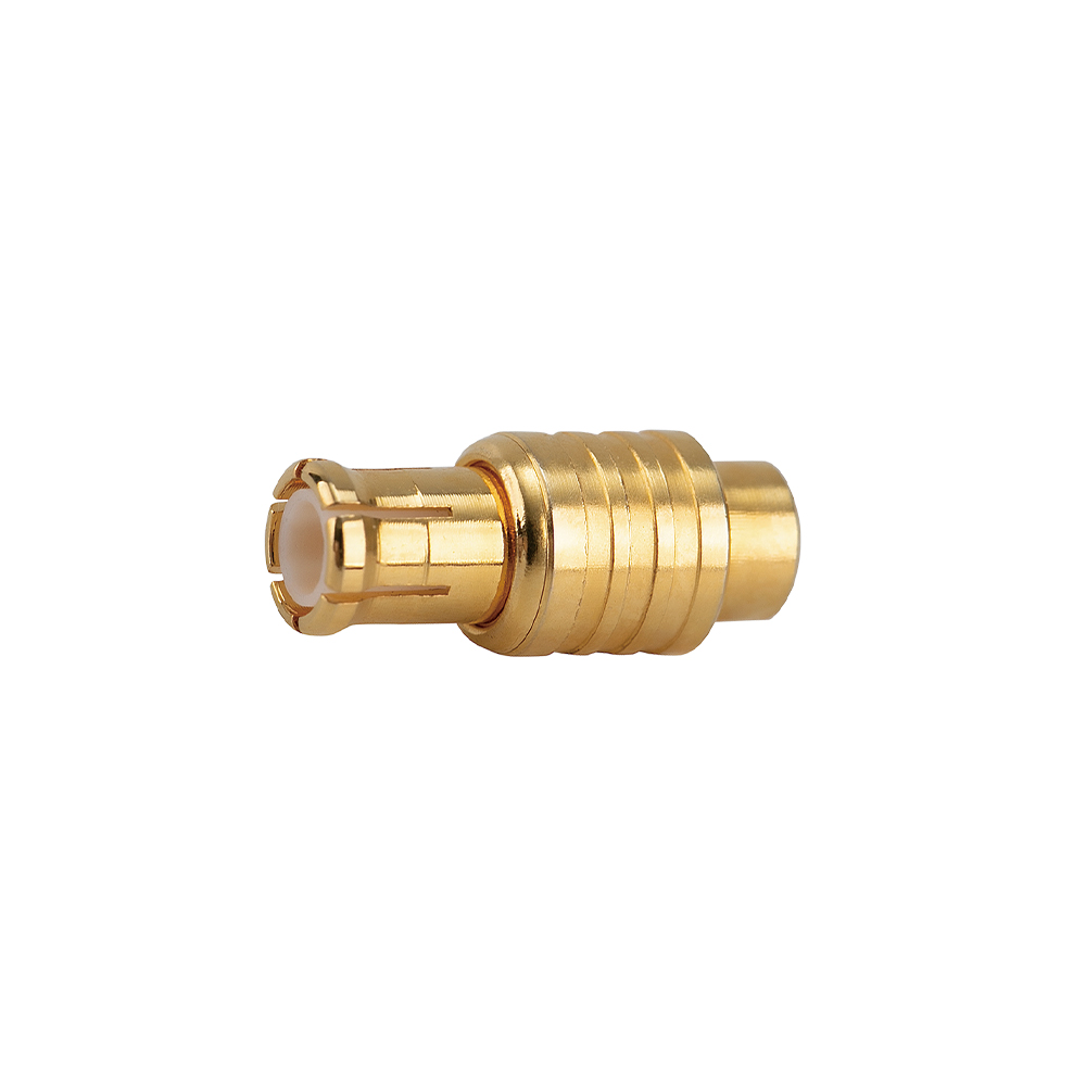
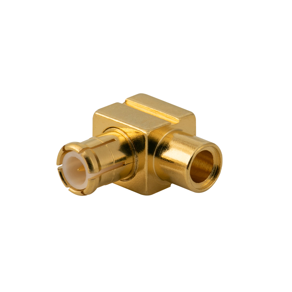
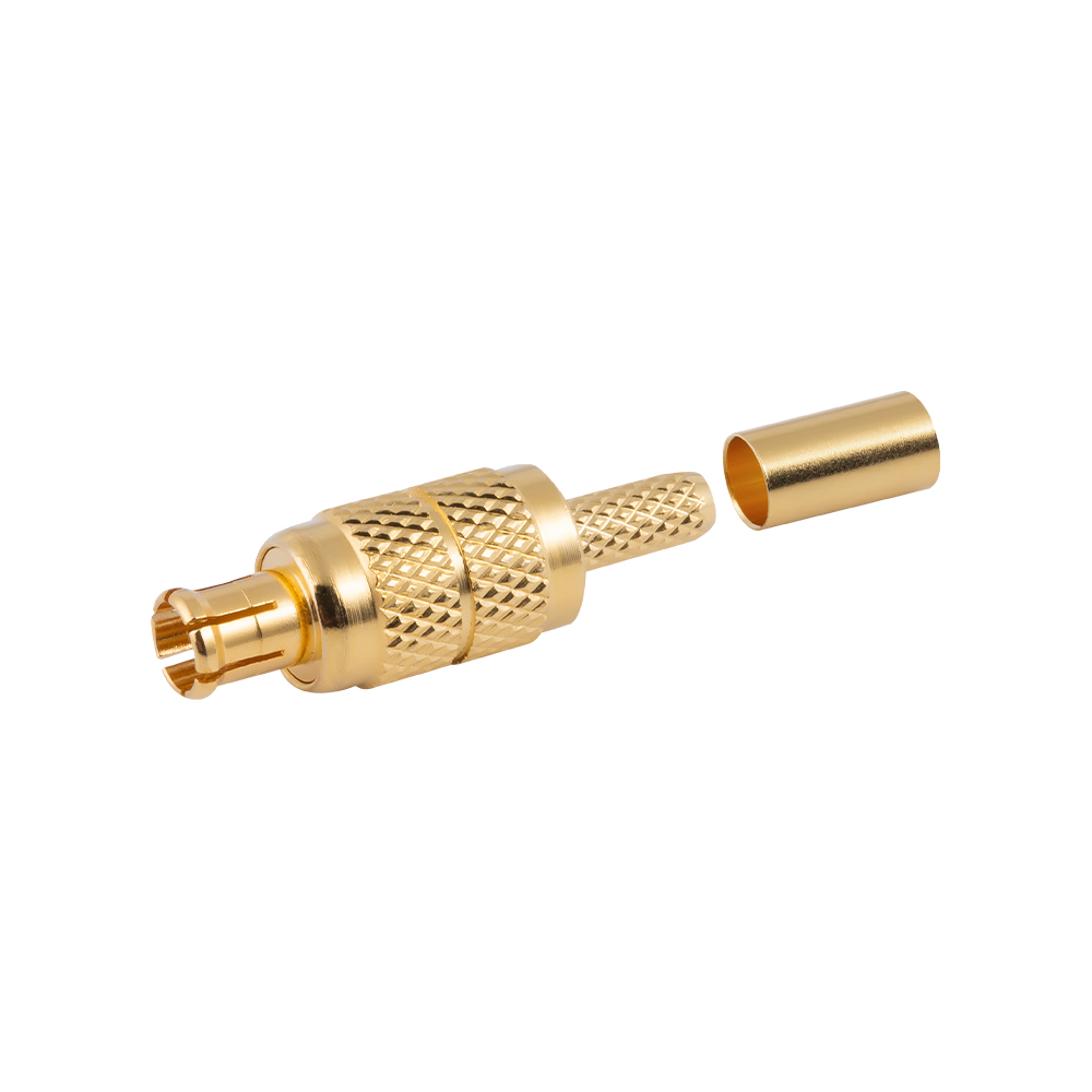
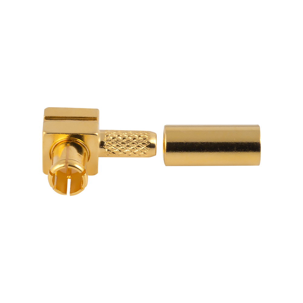
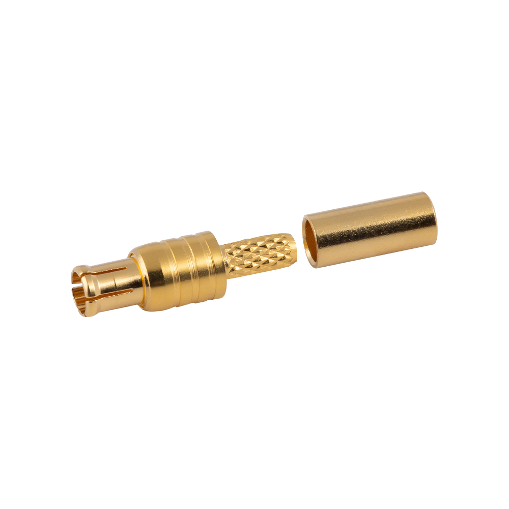
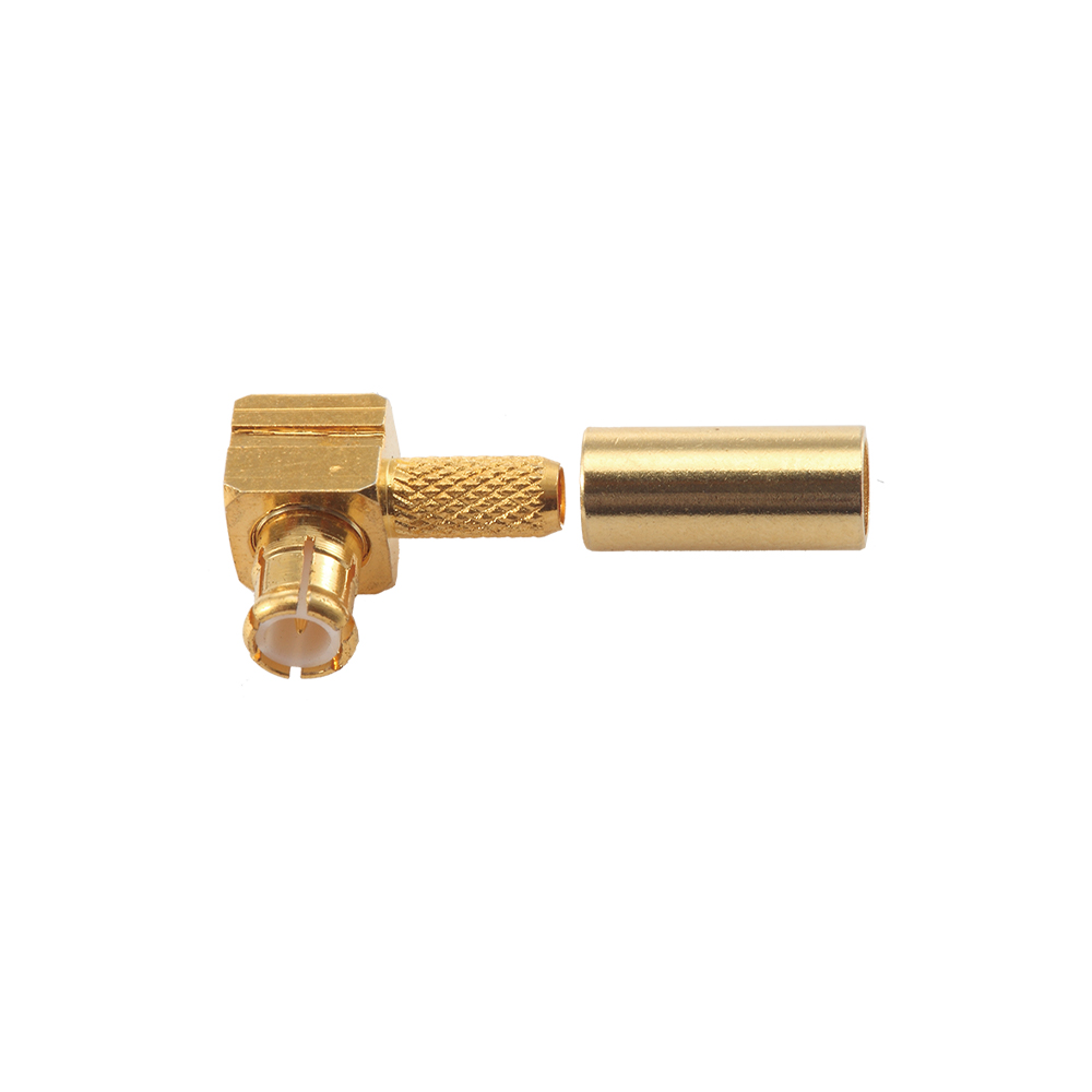
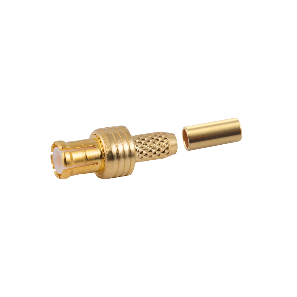
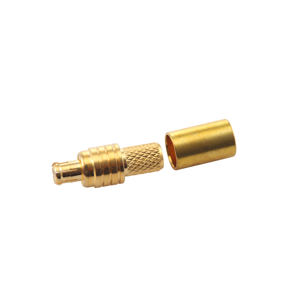
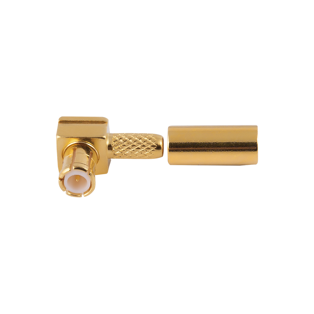
The 650.1731 SMA-C-JLMR240-1 is an SMA connector designed for flexible cable applications, combining the compact form factor, threaded coupling, and dependable radio-frequency performance expected from the SMA connector family. It is intended for use where a flexible coaxial cable must be terminated securely and connected to equipment, modules, antennas, test devices, or other RF assemblies. Its design is particularly relevant to applications that require stable impedance behavior, repeatable mating, mechanical reliability, and efficient installation.

In RF systems, the connector is not a minor accessory. It is part of the transmission line. The connector influences signal continuity, return loss, insertion loss, shielding effectiveness, mechanical durability, and the long-term stability of the complete cable assembly. A well-designed SMA connector must therefore provide more than a convenient interface. It must maintain a controlled electrical transition between the cable and the mating port while withstanding handling, vibration, environmental exposure, and repeated connection cycles.

The 650.1731 SMA-C-JLMR240-1 belongs to the category of SMA connectors for flexible cable. Its product designation identifies a specialized cable termination intended for an RF cable configuration associated with the JLMR240-1 cable type or equivalent construction, subject to the applicable engineering drawing and ordering specifications. As with any precision RF component, final compatibility should be confirmed against the cable outside diameter, dielectric structure, conductor dimensions, braid construction, connector interface, and assembly process.

This article examines the product’s role, design value, application advantages, manufacturing considerations, inspection requirements, and the capabilities of its manufacturer, Yangzhou Jingcheng Electronics Co., Ltd. It also explains why a purpose-designed flexible-cable SMA connector can outperform generic alternatives in demanding RF interconnection systems.

Content

Product Overview

The SMA interface is one of the most widely recognized threaded RF connector formats for compact microwave and radio-frequency equipment. It is commonly selected for its small size, robust threaded coupling, broad availability, and suitability for applications extending from general RF systems into higher-frequency designs when the connector geometry, materials, and assembly quality are properly controlled.

The 650.1731 SMA-C-JLMR240-1 is configured as an SMA cable connector. The “C” designation in the product name indicates a cable-side connector configuration within the manufacturer’s product nomenclature, while the remaining designation identifies the associated cable and construction variant. Exact gender, mounting orientation, plating, cable preparation dimensions, and electrical limits should be determined from the relevant product drawing or technical confirmation before production release.

Its main function is to establish a low-loss, shielded, and mechanically secure transition between a flexible coaxial cable and an SMA-compatible RF port. The connector must preserve the cable’s coaxial geometry through the termination region. It must also maintain a reliable contact between the center conductor and the mating contact, while creating a continuous outer-conductor path through the cable braid, connector body, and mating interface.

A flexible-cable connector differs from a connector intended for semi-rigid or rigid cable. Flexible coaxial cable may include a stranded center conductor, polymer dielectric, braided outer conductor, foil shielding, and an outer jacket. These layers can deform during stripping, crimping, soldering, or clamping. The connector must therefore be designed around the cable’s actual structure. A connector that appears dimensionally similar but is not matched to the cable may create poor contact pressure, excessive conductor deformation, impedance discontinuities, or unreliable pull strength.

Why Flexible-Cable SMA Termination Matters

Flexible coaxial cables are used when routing freedom is more important than the fixed geometry of a rigid transmission line. They are found in instrumentation, wireless equipment, industrial electronics, laboratory systems, antenna assemblies, communication devices, and internal equipment interconnections. During installation, these cables may need to pass around corners, accommodate enclosure tolerances, or connect moving subassemblies.

The flexibility that makes the cable convenient also creates challenges at the termination. Repeated bending close to the connector can transfer stress to the center contact or outer shield. Poorly controlled stripping can damage the dielectric or braid. Excessive crimp force can deform the cable and change its RF properties. Insufficient mechanical compression can result in low retention and intermittent shielding.

The 650.1731 SMA-C-JLMR240-1 is valuable because it is intended as a matched termination solution rather than a universal connector adapted to many unrelated cables. A cable-specific connector can provide more predictable assembly dimensions, more consistent retention, and better control of the electrical transition. This is particularly important in production environments where hundreds or thousands of assemblies must be manufactured with repeatable results.

A correctly assembled flexible-cable SMA connector should provide the following fundamental functions:

1. A stable center-contact connection with suitable contact force and low electrical resistance.

2. A continuous 360-degree or near-continuous shield transition, depending on the connector construction and cable design.

3. Mechanical retention that resists cable pull, twisting, and moderate bending loads.

4. A controlled dielectric transition that minimizes reflections and unwanted parasitic effects.

5. A secure threaded interface with the mating SMA connector.

6. Protection against accidental loosening during normal equipment use.

7. Efficient assembly using a defined preparation and termination procedure.

Core Performance Advantages

Controlled RF Continuity

The most important advantage of a purpose-built connector is controlled RF continuity. In a coaxial transmission line, the center conductor carries the signal while the outer conductor provides the return path and electromagnetic shielding. The spacing and geometry between these conductors influence the characteristic impedance. Any abrupt change in diameter, gap, dielectric material, or conductor position can cause a discontinuity.

The 650.1731 SMA-C-JLMR240-1 is engineered for a particular flexible-cable termination. This allows the connector’s center contact, dielectric support, rear cable interface, and outer body to be arranged around the cable geometry. Compared with an incorrectly matched generic SMA connector, a correctly specified part can reduce the risk of poor impedance transition and unstable high-frequency behavior.

Secure Threaded Coupling

SMA connectors use a threaded coupling mechanism that provides positive mechanical engagement. Unlike push-on connectors, a correctly tightened SMA connection is less likely to separate because of ordinary vibration, cable movement, or incidental contact. This makes the interface suitable for equipment that must maintain a stable RF path over time.

Threaded coupling also provides predictable mating force when the recommended torque is used. The connector body supports the interface while the coupling nut draws the mating faces together. Proper torque is important: insufficient torque may cause unstable contact or poor shielding, while excessive torque may damage threads, deform the interface, or shorten service life.

Compact RF Interconnection

Equipment designers often need to route several RF paths inside a limited enclosure. SMA connectors offer a practical balance between mechanical strength and compact size. The 650.1731 connector can support flexible cable routing without requiring the larger panel area associated with some higher-power or larger-format RF interfaces.

Its compact configuration can be useful in test equipment, communication modules, antenna feed systems, wireless infrastructure, and embedded RF assemblies. The space savings become especially valuable when several cables must be connected near one another or when a cable exits a crowded equipment compartment.

Improved Assembly Consistency

A cable-specific connector simplifies process control. The cable preparation dimensions can be defined, the tooling can be selected, and the termination sequence can be documented. Operators can then produce repeatable assemblies rather than adjusting a generic connector for every application.

Consistency is essential because RF failures are often caused by small variations that are difficult to detect visually. Examples include a braid strand entering the center-contact area, an incompletely seated dielectric, excessive stripping, insufficient crimp compression, or a center conductor that is not fully inserted. A connector supported by clear process instructions and suitable tooling reduces these risks.

Durable Shielding

The outer conductor of a coaxial cable performs two jobs: it completes the electrical return path and limits electromagnetic leakage. The cable-side portion of the SMA connector must preserve this function. A secure connection between the cable shield and connector body helps reduce susceptibility to external interference and limits unwanted radiation from the cable.

In measurement and communication systems, stable shielding can be just as important as center-conductor continuity. Poor shield termination may create noise, degraded isolation, unpredictable test results, or sensitivity to cable movement. A properly assembled connector helps maintain the shielding performance of the complete cable assembly.

Comparison with Generic or Lower-Quality Alternatives

Product selection should not be based only on the external appearance of an SMA connector. Many products may share the same nominal interface while differing significantly in cable compatibility, material quality, plating, dimensional control, assembly repeatability, and inspection standards.

A generic connector may be marketed as suitable for flexible coaxial cable but lack a precise match to the cable used in the project. Such a mismatch can lead to several problems. The center contact may not fit the conductor correctly. The rear ferrule may not compress the braid evenly. The dielectric support may leave a gap or apply excessive pressure. The connector may pass a basic continuity test while producing unacceptable RF performance at operating frequency.

The 650.1731 SMA-C-JLMR240-1 offers an advantage when the application uses the specified cable construction because the connector is selected as part of a defined cable-interface system. The result is more predictable than choosing an interchangeable-looking part solely by connector family.

Low-cost alternatives may also use inconsistent surface treatment or less carefully controlled base materials. The visible connector may appear acceptable while the mating surface, center contact, or internal support has inadequate dimensional stability. Over time, poor plating can contribute to corrosion, increased contact resistance, or deterioration after repeated mating.

Another difference is manufacturing support. A specialized connector manufacturer can provide engineering assistance, custom configurations, cable assembly guidance, and production feedback. This support is valuable when the connector must be integrated into a new device or when a cable termination process needs to be optimized.

Evaluation AreaPurpose-Designed Flexible-Cable SMA ConnectorGeneric or Poorly Matched Alternative
Cable compatibilityDeveloped around defined cable dimensions and constructionMay require adaptation or may not fit correctly
RF transitionBetter opportunity for controlled coaxial geometryGreater risk of discontinuities and reflections
Mechanical retentionCan be matched to the cable jacket, braid, and conductorMay slip, deform the cable, or provide uneven compression
Production repeatabilitySupports documented preparation and tooling proceduresMay depend heavily on operator adjustment
Shield terminationDesigned to establish a stable outer-conductor connectionMay leave gaps or produce inconsistent shielding
Quality controlCan be supported by dimensional, electrical, and visual inspectionInspection depth may be limited or inconsistent
Engineering supportSuitable for customization and application consultationOften limited to catalog-level information

Manufacturing Process and Engineering Control

The performance of an RF connector begins with manufacturing discipline. Precision connectors contain multiple components whose dimensions must work together. The center contact must align with the connector axis. Insulating components must position the contact accurately. The outer body must provide the correct mechanical interface. The cable-side region must retain the flexible cable without damaging its electrical structure.

Yangzhou Jingcheng Electronics Co., Ltd. specializes in the design, development, production, sales, and service of RF coaxial connectors and related products. Founded in 1999, the company has developed a broad product range covering more than 2,000 types of components and assemblies. Its product scope includes coaxial connectors, adapters, reverse polarity connectors, coaxial lightning protectors, high-frequency cables, cable assemblies, attenuators, terminal loads, antennas, and related RF interconnection products.

This broad product background is significant for the 650.1731 connector because flexible-cable connectors do not operate in isolation. They are commonly used with adapters, bulkhead connectors, cable assemblies, antennas, protective devices, and measurement equipment. A manufacturer experienced across these categories can evaluate the connector as part of a complete RF path.

Material Preparation

Manufacturing normally begins with the selection and preparation of conductive and insulating materials suitable for the intended connector construction. Conductive components may include copper alloys or other materials selected for electrical conductivity, mechanical strength, machinability, and plating compatibility. Insulating components must provide dimensional stability, suitable dielectric behavior, and resistance to the temperatures encountered during assembly and use.

Material selection affects both immediate performance and long-term reliability. A center contact requires a balance between conductivity and spring or retention characteristics. The connector body must maintain thread accuracy and interface geometry. The cable-support components must resist deformation while applying controlled mechanical force.

Precision Machining and Forming

Connector bodies and contact components are produced through controlled machining, forming, or a combination of manufacturing methods. Critical dimensions include the mating interface, thread geometry, center-contact location, cable-entry dimensions, and internal shoulders that position insulating parts.

For RF components, dimensional accuracy is not merely a cosmetic requirement. A small variation in the internal coaxial structure can affect impedance and return loss. Thread inaccuracies can reduce mating consistency or cause premature wear. Burrs, sharp edges, or incomplete surface finishing can damage the cable during installation.

Advanced production equipment supports repeatable manufacturing of these features. Process control may include machine setup verification, tool wear monitoring, first-piece inspection, in-process dimensional checks, and final sampling. These practices help ensure that connector components remain within the tolerances required for assembly and field performance.

Surface Treatment and Plating

Surface treatment is an important part of connector manufacturing. The selected finish must support electrical contact, corrosion resistance, solderability where applicable, wear resistance, and visual consistency. Mating surfaces require special attention because repeated connection and disconnection can gradually wear the finish.

Plating quality depends on preparation, cleaning, bath control, thickness management, rinsing, drying, and inspection. A reliable production system controls these stages to reduce the risk of poor adhesion, uneven coverage, contamination, or premature discoloration. The exact finish used for the 650.1731 connector should be confirmed in the applicable technical documentation, especially when the product is intended for harsh environments or repeated mating.

Insulator and Center-Contact Assembly

The center contact and insulating components must be assembled concentrically. Misalignment can increase contact wear, create an uneven electrical transition, or prevent proper mating. The insulator must hold the center contact securely while preserving the designed spacing between the center and outer conductors.

During assembly, cleanliness is essential. Conductive particles, machining residue, plating debris, or damaged dielectric material may impair RF performance. Controlled work areas, appropriate cleaning procedures, and visual inspection help limit these risks.

Cable Interface Assembly

The cable-side termination is the most application-specific part of the product. The installer must prepare the cable in accordance with the required strip dimensions. The outer jacket, braid, foil, dielectric, and center conductor must be exposed in the correct sequence and length.

The connector is then installed using the specified method, which may involve crimping, soldering, or a combination of mechanical and electrical attachment techniques depending on the design. The objective is to secure each cable layer without changing the coaxial geometry more than necessary.

A controlled assembly process should define:

1. Cable cutting requirements and acceptable end-face condition.

2. Jacket stripping length and permissible jacket damage.

3. Braid preparation and folding or placement method.

4. Dielectric stripping dimensions and center-conductor exposure.

5. Center-contact installation force or soldering requirements.

6. Ferrule or sleeve positioning.

7. Crimp-tool type, die size, and crimp location.

8. Inspection criteria for braid capture and cable seating.

9. Electrical continuity and RF test requirements.

10. Pull-force or mechanical retention verification where required.

When these steps are documented and followed, production personnel can achieve much more consistent results than when connectors are installed using informal techniques.

Quality Assurance and Testing

RF connector quality is evaluated through a combination of dimensional, visual, mechanical, and electrical checks. No single test is sufficient for every application. A connector can pass a continuity test and still have poor RF performance. It can show acceptable insertion loss while having inadequate cable retention. A complete quality program therefore examines multiple characteristics.

Dimensional Inspection

Dimensional inspection verifies critical interface features, cable-entry dimensions, thread characteristics, and overall geometry. Gauges, precision measuring tools, optical systems, and coordinate measurement equipment may be used depending on the feature and production requirement.

For an SMA connector, dimensional control of the mating interface is especially important. The connector must mate correctly with compatible SMA products without excessive looseness, interference, or abnormal contact force. Cable-side dimensions must also correspond to the intended flexible cable.

Visual Inspection

Visual inspection can identify damaged threads, scratches, burrs, plating defects, contamination, incomplete assembly, and cable termination problems. Inspectors may examine the center contact for correct position, the dielectric for damage, and the braid for proper capture.

Visual inspection is particularly valuable after cable assembly. Common defects include exposed center conductor that is too long, a displaced dielectric, stray braid strands, incomplete crimping, jacket intrusion into the contact area, and a ferrule that is not fully seated.

Continuity and Insulation Testing

Basic electrical testing confirms that the center conductor and outer conductor form the intended circuits and that there is no short circuit between them. Insulation resistance testing may also be applied where appropriate. These tests are fast and suitable for production screening, although they do not replace RF testing.

RF Performance Testing

RF testing may include insertion loss, return loss, voltage standing wave ratio, isolation, and frequency response. The exact test range should correspond to the application and the specified product performance. Test fixtures, calibration quality, cable movement, connector torque, and measurement repeatability all influence the result.

For reliable evaluation, the connector should be tested using a defined mating procedure and suitable calibration standards. The test setup must minimize errors caused by damaged interfaces, poorly assembled test cables, or inconsistent torque. When cable assemblies are tested, the connector should be evaluated as part of the complete assembly rather than as an isolated component only.

Mechanical Testing

Mechanical checks may include cable pull testing, torque testing, vibration exposure, flexing, mating-cycle evaluation, and environmental conditioning. The appropriate test depends on the end application. A laboratory cable, an outdoor antenna assembly, and an industrial control unit may require different mechanical validation levels.

Mechanical testing is important because RF performance can change after the connector or cable has been exposed to stress. A robust termination should maintain continuity, shielding, and acceptable RF performance after the expected handling and installation conditions.

Installation Recommendations

The 650.1731 SMA-C-JLMR240-1 should be installed only with the cable type and preparation dimensions for which it is specified. Before production, the user should confirm the cable part number, outside diameter, conductor size, dielectric construction, braid design, jacket material, and connector assembly method.

The cable should be cut squarely and kept clean. An angled or crushed cable end can make it difficult to achieve proper concentricity. During stripping, the installer should avoid nicking the center conductor, cutting through excessive braid, or damaging the dielectric. Even small defects can affect both mechanical strength and RF behavior.

The center contact should be installed to the specified seating position. If soldering is required, the process should control heat, solder quantity, and heating time. Excessive heat can deform the dielectric or damage the cable jacket. Too little solder or incomplete wetting can create a weak or intermittent joint.

When crimping is used, the correct tool and die must be selected. A crimp that is too loose may allow cable movement and poor shield continuity. A crimp that is too tight may crush the dielectric, deform the cable, or create an impedance discontinuity. The finished crimp should be visually uniform and positioned according to the assembly drawing.

During final mating, the connector should be aligned without forcing the threads. The coupling nut should be tightened using the recommended method and torque. The cable itself should not be used as a lever to tighten the connector. After installation, the cable should be supported so that bending loads are not concentrated directly at the connector exit.

Application Areas

Wireless Communication Equipment

SMA cable connectors are widely used in wireless communication equipment, including radio modules, transceivers, signal distribution units, and antenna interfaces. The threaded interface is useful where a stable connection must be maintained despite equipment movement or vibration.

Test and Measurement Systems

Laboratory instruments and production test fixtures frequently use SMA connections because they provide a compact, familiar, and repeatable RF interface. Flexible cable assemblies allow test ports and internal connections to be routed around instruments while maintaining a serviceable connection.

Antenna Assemblies

Antennas often require a flexible cable connection between the radiating element and a radio, amplifier, filter, or enclosure-mounted port. A purpose-designed flexible-cable SMA connector can provide a practical transition while allowing the cable to be routed through constrained spaces.

Industrial and Embedded Electronics

Industrial sensors, wireless gateways, navigation equipment, control systems, and embedded communication devices may use SMA connectors for external or internal RF paths. In these applications, stable mechanical retention and predictable assembly are important because maintenance access may be limited.

High-Frequency Cable Assemblies

The connector can also serve as a component in custom RF cable assemblies. A cable assembly manufacturer may combine the 650.1731 connector with another SMA, an adapter, a bulkhead interface, a lightning protection device, or a specialized antenna connector. The final assembly can be configured to meet particular length, routing, environmental, and installation requirements.

Manufacturer Strengths

Yangzhou Jingcheng Electronics Co., Ltd. brings several strengths to the manufacture and supply of RF connector products. Its history since 1999 demonstrates long-term involvement in the interconnection field. Its product range of more than 2,000 types indicates experience with multiple connector families, cable configurations, protective components, and RF accessories.

The company’s capabilities include product design, development, manufacturing, sales, and service. This integrated structure can improve communication between engineering and production. When customers require a modified connector, special cable length, different interface, alternate plating, customized packaging, or a complete cable assembly, an integrated supplier is generally better positioned to evaluate the request.

The company also emphasizes advanced manufacturing and testing equipment, technical capability, quality systems, and professional research and development and engineering teams. These strengths are relevant to the 650.1731 product because RF connectors require coordination between mechanical design, materials, machining, surface treatment, assembly, and electrical validation.

A broad product portfolio also supports system-level problem solving. For example, a customer designing an RF enclosure may need an SMA cable connector, a panel adapter, a coaxial lightning protector, a reverse polarity connector, and a finished cable assembly. Working with a supplier that understands these related product categories can simplify technical coordination and reduce compatibility risks.

Customization and Project Support

Standard catalog products are appropriate for many applications, but some projects require modifications. These may involve a different cable, connector orientation, mounting arrangement, cable length, interface type, environmental requirement, or packaging configuration. Customization should be based on a clear technical specification rather than a visual comparison with an existing part.

Important information for a custom or project-based inquiry includes the cable model, electrical impedance, operating frequency, required length, connector interfaces, gender, mounting method, environmental conditions, expected mating cycles, power level, and applicable standards. Drawings, samples, and test requirements can further improve the accuracy of engineering evaluation.

For the 650.1731 SMA-C-JLMR240-1, the user should confirm whether the intended cable is exactly the specified JLMR240-1 type or an equivalent cable with matching dimensions. Even cables with similar names may differ in dielectric diameter, braid coverage, jacket thickness, or center-conductor construction. These differences can affect assembly and performance.

Procurement and Lifecycle Considerations

When purchasing RF connectors, the lowest unit price does not always represent the lowest total cost. A connector that requires excessive assembly adjustment, produces a high rejection rate, or causes field failures may create greater expense than a more carefully specified component.

The 650.1731 connector should be evaluated according to the total application requirement. Relevant considerations include connector consistency, cable compatibility, assembly labor, tooling, inspection time, rework rate, field reliability, supply continuity, and technical support. A stable supply of a correctly matched connector can improve production planning and reduce variation between batches.

For ongoing projects, purchasers should maintain control of the approved product designation, revision level, drawing, material requirements, inspection criteria, and packaging conditions. Substitutions should not be made solely because another connector has the same nominal SMA interface. The cable-side design and internal geometry may be different.

Storage conditions also matter. Connectors should be protected from contamination, moisture, excessive temperature, and mechanical damage. Threaded interfaces should remain capped or packaged when practical. Cable assemblies should not be stored with tight bends that place long-term stress on the termination.

Q&A

What is the 650.1731 SMA-C-JLMR240-1?

It is an SMA connector for flexible cable, identified by the product designation 650.1731 SMA-C-JLMR240-1. It is intended to terminate a compatible flexible coaxial cable and provide an SMA interface for RF equipment, cable assemblies, antennas, instruments, and related systems.

What cable should be used with this connector?

The connector should be used with the cable type specified in the applicable product documentation, identified in the designation as JLMR240-1. The user should verify cable dimensions and construction before ordering or assembly. A visually similar cable may not have the same conductor, dielectric, braid, or jacket dimensions.

What are the main advantages of a cable-specific SMA connector?

A cable-specific connector can provide better compatibility, more predictable RF continuity, stronger mechanical retention, improved shielding, and more repeatable production assembly than a generic connector that has not been matched to the cable.

Is the connector suitable for high-frequency applications?

SMA connectors are commonly used in RF and microwave systems. Suitability depends on the complete product design, cable, assembly quality, operating frequency, and test requirements. The user should confirm the specified frequency range, return loss, insertion loss, and other electrical characteristics for the intended application.

How should the connector be assembled?

Assembly should follow the manufacturer’s drawing or work instruction. The process generally includes precise cable cutting, controlled stripping, center-contact installation, shield and ferrule placement, crimping or soldering as applicable, and final inspection. Correct tooling and strip dimensions are essential.

Can the connector be used in outdoor equipment?

It may be used in outdoor equipment when the complete connector, cable assembly, enclosure, sealing method, and environmental protection system meet the application requirements. Outdoor use may require protection against moisture, corrosion, temperature variation, ultraviolet exposure, vibration, and contaminants.

Does a continuity test prove that the RF assembly is acceptable?

No. Continuity testing confirms basic electrical connection but does not fully evaluate impedance, return loss, insertion loss, shielding, or frequency response. RF testing should be performed when the application requires controlled high-frequency performance.

Why is proper SMA tightening important?

Correct tightening helps establish stable mating contact and shielding. Under-tightening may cause an unstable connection, while over-tightening may damage the threads or interface. The recommended torque and procedure should be followed for the connector and mating component.

Can Yangzhou Jingcheng Electronics provide customized solutions?

The company specializes in RF connectors, cable assemblies, adapters, lightning protectors, antennas, and related products, and provides design, development, production, sales, and service. Customers should submit the cable, interface, electrical, mechanical, environmental, and quantity requirements for project evaluation.

What should be confirmed before placing a production order?

The purchaser should confirm the exact product designation, drawing revision, cable compatibility, connector interface, plating or finish, electrical requirements, assembly method, inspection requirements, packaging, quantity, and delivery schedule. Samples or first-article approvals may be appropriate for new applications.

Conclusion

The 650.1731 SMA-C-JLMR240-1 is a specialized SMA connector for flexible cable applications where compact size, secure threaded coupling, controlled RF continuity, and repeatable assembly are important. Its principal value comes from matching the connector design to the intended flexible coaxial cable rather than treating the SMA interface as a universal, interchangeable component.

Compared with poorly matched or lower-quality alternatives, a correctly specified connector can improve cable retention, shielding continuity, assembly consistency, and confidence in the complete RF path. Its performance depends not only on the connector itself but also on accurate cable preparation, suitable tooling, correct mating technique, and appropriate electrical and mechanical inspection.

Yangzhou Jingcheng Electronics Co., Ltd. supports this product through long-term experience in RF interconnection technology, a portfolio of more than 2,000 related product types, engineering and research capabilities, advanced manufacturing and testing equipment, and quality-focused production systems. These capabilities make the company suitable for standard connector supply as well as customized RF interconnection projects.

For designers, manufacturers, and procurement teams, the recommended approach is to evaluate the 650.1731 SMA-C-JLMR240-1 as part of a complete cable and equipment interface. Confirm the cable construction, electrical requirements, mechanical constraints, environmental conditions, and assembly procedure before release. When these factors are controlled, the connector can contribute to a stable, serviceable, and efficient RF interconnection system.
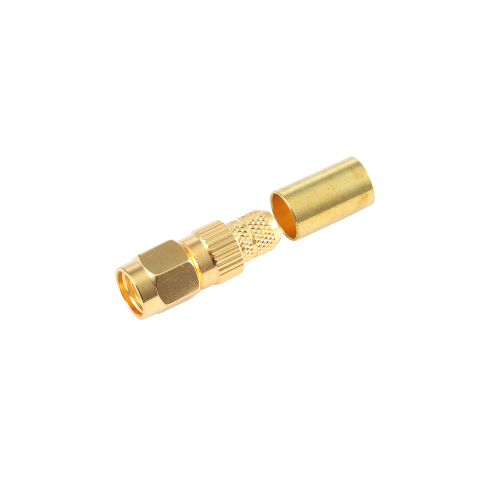
650.1731 SMA-C-JLMR240-1

References

1. International Electrotechnical Commission, radio-frequency connector terminology and interface practice, applicable technical standards.

2. Institute of Electrical and Electronics Engineers, recommended practices for RF transmission, impedance control, and measurement accuracy.

3. Mechanical and electrical design principles for coaxial connectors and cable assemblies, professional RF engineering reference materials.

4. Manufacturer technical documentation for SMA connectors, flexible coaxial cable interfaces, assembly procedures, and inspection requirements.

5. General quality-management principles for precision electronic connector manufacturing and process control.

Product: 650.1731 SMA-C-JLMR240-1


Related products
JC3.650.067 MCX-JWB2
VIEW MORE
JC3.650.068 MCX-JWB3
VIEW MORE
JC3.650.069 MCX-JB2
JC3.650.069 MCX-JB2
JC3.650.069 MCX-JB2
JC3.650.069 MCX-JB2
VIEW MORE
JC3.650.1844  MCX-JB2-3
JC3.650.1844 MCX-JB2-3
JC3.650.1844  MCX-JB2-3
JC3.650.1844 MCX-JB2-3
VIEW MORE
JC3.650.1854  MCX-JWB2-5
JC3.650.1854 MCX-JWB2-5
JC3.650.1854  MCX-JWB2-5
JC3.650.1854 MCX-JWB2-5
VIEW MORE
JC3.650.622  MCX-C-75J1.5
JC3.650.622 MCX-C-75J1.5
JC3.650.622  MCX-C-75J1.5
JC3.650.622 MCX-C-75J1.5
VIEW MORE
JC3.650.1301  MCX-C-75JW1.5
JC3.650.1301 MCX-C-75JW1.5
JC3.650.1301  MCX-C-75JW1.5
JC3.650.1301 MCX-C-75JW1.5
VIEW MORE
JC3.650.1307  MCX-C-75J1.5-1
JC3.650.1307 MCX-C-75J1.5-1
JC3.650.1307  MCX-C-75J1.5-1
JC3.650.1307 MCX-C-75J1.5-1
VIEW MORE
JC3.650.059  MCX-C-JW1.5
JC3.650.059 MCX-C-JW1.5
JC3.650.059  MCX-C-JW1.5
JC3.650.059 MCX-C-JW1.5
VIEW MORE
JC3.650.062 MCX-C-J1.5
VIEW MORE
JC3.650.066  MCX-C-J3
JC3.650.066 MCX-C-J3
JC3.650.066  MCX-C-J3
JC3.650.066 MCX-C-J3
VIEW MORE
JC3.650.076  MCX-C-JW1.5-4
JC3.650.076 MCX-C-JW1.5-4
JC3.650.076  MCX-C-JW1.5-4
JC3.650.076 MCX-C-JW1.5-4
VIEW MORE
News & Updates
Coaxial Cable Selection Guide: Choosing Cable, Connectors, and RF Performance
Industry News
2026-08-21
Coaxial Cable Selection Guide: Choosing Cable, Connectors, and RF Performance
An RF engineer once told me that most field failures are not component failures; they are selection failures. Selecting a coaxial cable starts with three decisions: characteristic impedance, cable size, and connector family. Get these three right and the rest of the design has a predictable signal path. Get one wrong and you will be debugging intermittent reflections for weeks. A coaxial cable and its connector are one assembly, not two parts. A properly matched pair keeps the impedance continuous from the PCB to the antenna or instrument port, while an unmatched combination creates reflections, heating, and intermittent signals. That is why this guide treats the cable and its termination as a single selection process. What a Coaxial Cable Is and Why Geometry Matters A coaxial cable is a cylindrical signal carrier made of four concentric layers: inner conductor, dielectric spacer, conductive shield, and protective jacket; its characteristic impedance is fixed by the ratio of the inner conductor diameter to the shield diameter. Change that ratio, or change the dielectric, and the impedance changes even if the outer diameter stays the same. The same geometry also controls attenuation and power handling. Larger cables generally have lower loss and higher power capability, but they cost more, weigh more, and bend less easily. This trade-off is the starting point of every practical selection. Choose 50 Ohm for RF and 75 Ohm for Video Distribution Use 50 ohm whenever the signal is RF, microwave, or telecommunications, and use 75 ohm for video, broadcast, and cable television distribution. The 50 ohm value is a practical compromise between low attenuation and higher power handling, while 75 ohm reduces loss at video frequencies and has become the standard impedance for CATV infrastructure. Mixing impedance systems is possible over very short lengths but normally costs return loss. A 75 ohm cable inserted into a 50 ohm system creates a small impedance bump at every transition, which degrades VSWR and adds ripple to the passband. 50 ohm and 75 ohm coaxial systems: typical applications and characteristics Impedance Market Typical Cables Connector Families 50 ohm RF/microwave, mobile, Wi-Fi, GPS, test RG-58, RG-174, RG-213, semi-rigid SMA, N, TNC, BNC, 7-16 75 ohm CCTV, cable TV, broadcast video RG-59, RG-6, RG-11 F, BNC, RCA Key Cable Parameters: Loss, Power, Shielding, and Flexibility Compare four electrical parameters first: attenuation, power handling, shielding effectiveness, and impedance stability; then add mechanical flexibility and environmental rating. Attenuation rises with frequency, so a cable selected for 100 MHz can become unusable at 2.4 GHz. For example, a 10-meter run of RG-58 at 900 MHz can lose on the order of 6 to 7 dB, while RG-213 of the same length loses roughly 2 to 3 dB. The larger conductor and dielectric simply dissipate less RF energy. RG-174 is thinner and lossier than RG-58, which makes it suitable for short pigtail connections rather than long feeder runs. Representative RG-style cables; loss trend is relative, not a fixed value Cable Impedance Diameter Flexibility Typical Use Loss Trend RG-58 50 ohm About 5 mm Good Test leads, short RF jumpers Moderate RG-174 50 ohm About 2.5 mm Very good Internal module wiring, GPS pigtails Higher RG-213 50 ohm About 10 mm Stiff Base station feeders, higher power Lower RG-6 75 ohm About 7 mm Good CATV, satellite, long video runs Lower RG-59 75 ohm About 6 mm Good CCTV, short video links Moderate RG-11 75 ohm About 10 mm Stiff Long CATV drops Lower Connector Selection: Match the Cable Bore, Frequency, and Environment The connector is the most failure-prone part of an RF coaxial assembly, so select it by impedance, frequency range, mechanical coupling, and the exact cable diameter it was designed to fit; then verify plating, torque, and sealing before production. Most connector families are available in versions for flexible and semi-rigid cables, and a good series is rated higher than your actual operating frequency because it is rarely a perfect 50 or 75 ohm line. Before finalizing the connector family, cross-check the full specification matrix with our RF coaxial connector selection guide, which covers types, specifications, and selection tips in more detail. Common coaxial connector families and their typical applications Connector Impedance Frequency Typical Cable Use BNC 50 / 75 ohm Up to 4 GHz RG-58, RG-59 Test instruments, video TNC 50 ohm Up to 11 GHz RG-58, RG-213 Vibration-resistant outdoor links N 50 ohm Up to 11 GHz RG-213, low-loss flexible, semi-rigid Outdoor antennas, feeders SMA 50 ohm Up to 18 GHz RG-58, RG-174, semi-rigid Module ports, test equipment MCX / MMCX 50 ohm Up to 6 GHz Micro-coax Compact PCB-to-antenna links 7-16 DIN 50 ohm Up to 7.5 GHz Large-diameter feeders Base stations, high power When the cable run feeds an outdoor antenna, N type RF coaxial connectors provide weather-resistant construction and stable electrical performance across the cellular and Wi-Fi bands. For compact RF modules and test ports, SMA RF coaxial connectors remain the default interface up to 18 GHz. And for base station transmitters, 7-16 DIN RF coaxial connectors keep insertion loss and intermodulation low at high power levels. Wholesale 7/16(L29) RF Coaxial Connectors Manufacturer, FactoryYangzhou Jingcheng Electronics Co., Ltd. is China 7/16(L29) RF Coaxial Connectors manufacturer and 7/16(L29) RF Coaxial Connectors factor...View Product →Wholesale SMA RF Coaxial Connectors Manufacturer, FactoryYangzhou Jingcheng Electronics Co., Ltd. is China SMA RF Coaxial Connectors manufacturer and SMA RF Coaxial Connectors factory, we offeri...View Product →Wholesale N RF Coaxial Connectors Manufacturer, FactoryYangzhou Jingcheng Electronics Co., Ltd. is China N RF Coaxial Connectors manufacturer and N RF Coaxial Connectors factory, we offering w...View Product → Shielding and Dielectric Choice Affect Noise Immunity and Stability Shielding determines how much external noise reaches the inner conductor and how much signal leaks out; in crowded environments or high-speed data paths, use double-shielded or foil-plus-braid constructions rather than single braid. A foil layer blocks high-frequency noise while a braided layer provides mechanical strength and low-resistance grounding. The dielectric is just as important: solid polyethylene is economical but lossier at microwave frequencies, while foam or PTFE dielectrics lower attenuation at higher cost. Foam dielectric is lighter and more flexible but more sensitive to crushing and moisture, so reserve it for indoor runs and choose solid dielectric for outdoor or high-vibration paths. Application-Based Selection Summary The fastest way to select a cable is to start from the installation environment and let RF requirements narrow the cable and connector family: long outdoor runs prioritize attenuation and weather sealing, module-level wiring prioritizes size and flexibility, and test setups prioritize repeatable impedance and stable connector torque. Base station feeder Use 7-16 DIN or N connectors with a low-loss foam-dielectric cable; verify intermodulation performance. Test and measurement Use SMA connectors with semi-rigid cable, and check VSWR stability under repeated flexing and torque. IoT and portable devices Use MMCX or MCX with micro-coax to save board space and allow a light, flexible antenna pigtail. CCTV and video Use RG-59 or RG-6 with BNC connectors, keeping the system at 75 ohm to avoid visible signal artifacts. Outdoor antenna feed Use N connectors with a double-shielded flexible cable and a weatherproofed joint at the antenna. Microwave board interconnect Use SMP or 2.92 mm connectors with semi-rigid cable to control performance above 10 GHz. Practical Purchasing Considerations for Production For volume orders, verify mechanical tolerances, plating quality, and lot-to-lot impedance consistency rather than relying only on the datasheet; a connector that works on a prototype bench can fail in the field if the cable center conductor diameter sits at the edge of the connector crimp range. Ask your supplier for mating dimension checks, cable retention force, and environmental documentation. A dedicated RF connector manufacturer with a broad catalog can also reduce your vendor count, especially when interconnections become complex. A small, clearly identified set of intertype RF adapters covers unusual transitions during bring-up and test, so you do not need to re-cable a working setup for a single measurement. Coaxial Cable Selection FAQ Can I use a 75 ohm cable in a 50 ohm system? Short temporary jumpers work, but the mismatch adds return loss and can create ripple in tight-bandwidth systems. Avoid this combination for production or for any link that requires stable VSWR. What is the difference between RG-6 and RG-59? RG-6 has a larger conductor and lower attenuation, making it a better choice for satellite, long cable runs, and high-frequency video; RG-59 is thinner, cheaper, and still adequate for short CCTV links. Which connector is best for outdoor use? N type connectors are the usual outdoor standard for RF because of their sealed construction and stable performance; TNC is also suitable when vibration is a concern. Confirm the specific connector has an IP-rated or weatherized version. How do I match a connector to my cable? Check the connector datasheet for the supported cable diameter and dielectric outer diameter, not just the series name such as SMA or N. The cable and connector must share the same impedance and the connector must suit the cable’s outer jacket size. Does cable length affect impedance? No. Impedance is a per-unit property of the cable construction. Length affects total attenuation, phase, and DC resistance, but it does not change the nominal characteristic impedance. Final Selection Checklist Before approving a sample for production, run through these checks: Confirm system impedance is 50 or 75 ohm and the cable matches. Verify attenuation and power handling at the highest operating frequency. Match connector series to cable diameter and frequency range. Select shielding for the noise environment and double-check leakage requirements. Consider jacket material, temperature rating, and bend radius for outdoor or flexing installs. Validate connector torque, crimp tooling, and lot-to-lot consistency with the actual cable. A coaxial cable is rarely the most expensive part of an RF system, yet it is one of the most common sources of field rework. Choosing impedance, cable class, and connector family carefully on the first pass saves test time, assembly rework, and final test failures. article{font-family:Georgia,'Times New Roman',serif;font-size:17px;line-height:1.85;color:#1f242b;padding:0 20px;margin:0 auto;} .article-section table{display:table!important;width:100%;border-collapse:collapse;margin-bottom:20px;font-size:15px;} .article-section thead{display:table-header-group!important;} .article-section tbody{display:table-row-group!important;} .article-section tr{display:table-row!important;} .article-section th{display:table-cell!important;font-weight:bold;border:1px solid #cccccc;padding:8px;background:#f4f6f8;} .article-section td{display:table-cell!important;border:1px solid #cccccc;padding:8px;} .article-section caption{caption-side:bottom;font-size:16px;margin-bottom:12px;font-style:italic;color:#808080;} .article-section ol{margin-bottom:12px;list-style-type:decimal;list-style-position:inside;padding-left:0;} .article-section ul{margin-bottom:12px;list-style-type:disc;list-style-position:inside;} .article-section li{list-style:inherit;font-size:16px;margin-bottom:6px;} .article-section h2{font-size:1.55em;font-weight:bold;text-align:left;margin-top:40px;margin-bottom:10px;border-left:5px solid #0077cc;padding-left:14px;color:#0a2a4a;} .article-section h3{font-size:1.2em;font-weight:bold;text-align:left;margin-top:28px;margin-bottom:8px;color:#0a2a4a;} .article-section p{font-size:16px!important;margin-bottom:12px;} .card-grid{display:grid;grid-template-columns:repeat(auto-fit,minmax(240px,1fr));gap:16px;margin:20px 0;} .card{background:#f8fafc;border:1px solid #e2e8f0;border-radius:8px;padding:16px;} .article-section a{color:#0077cc;} .product-card{display:block;margin:20px 0;border:1px solid #e5e7eb;border-radius:10px;overflow:hidden;font-style:normal;background:#fff} .pc-inner{display:flex;text-decoration:none;color:inherit;align-items:center;min-height:120px} .pc-img{width:160px;min-width:160px;aspect-ratio:4/3;height:auto;min-height:120px;object-fit:cover;flex-shrink:0;display:block;align-self:stretch} .pc-body{padding:12px 16px;flex:1;min-width:0;display:flex;flex-direction:column;align-self:stretch;justify-content:center} .pc-title{display:block;font-size:15px;font-weight:600;color:#111;margin:0 0 6px;line-height:1.4} .pc-desc{display:-webkit-box;font-size:13px;color:#6b7280;margin:0 0 8px;line-height:1.5;overflow:hidden;-webkit-line-clamp:2;line-clamp:2;-webkit-box-orient:vertical} .pc-cta{display:block;font-size:13px;font-weight:600;color:inherit;margin-top:auto} .pc-inner:hover .pc-title{text-decoration:underline} .article-section a:not(.pc-inner),article a:not(.pc-inner){color:inherit}.pc-cta{color:inherit!important}...
Coax Cable Comparison: RG58 vs RG59 vs RG6 vs RG11 and Connector Matching
Industry News
2026-08-14
Coax Cable Comparison: RG58 vs RG59 vs RG6 vs RG11 and Connector Matching
Choosing a coaxial cable without comparing impedance, attenuation, and connector compatibility usually ends in poor signal quality. The practical rule is short: 50 Ω cables such as RG58 are for radio equipment, test instruments, and compact RF modules, while 75 Ω cables such as RG59, RG6, and RG11 are for video, TV, satellite, and broadband. Inside each impedance family, the decision comes down to run length, operating frequency, and how easily the cable must bend and terminate. This coax cable comparison covers the four most common RG cables, explains the numbers that matter, and maps each cable to the connector series that will actually fit it. What a Coax Cable Comparison Must Cover Six parameters determine whether a cable will work in your application: characteristic impedance, attenuation per unit length, frequency ceiling, outer diameter, flexibility, and shielding quality. Of these, impedance and attenuation cause the most mis-buys. Characteristic impedance — 50 Ω is the standard for RF systems, test equipment, and antennas; 75 Ω is the standard for video, TV, and broadband. Mismatches create reflections and extra loss. Attenuation — Measured in dB per 100 feet or per metre, attenuation climbs as frequency rises. A cable that works at 10 MHz can be unusable at 2.4 GHz over the same distance. Frequency ceiling — The highest usable frequency before loss or dimensional instability makes the cable impractical. Outer diameter and flexibility — Thick cables such as RG11 have low loss but a large bend radius; thin cables such as RG58 route easily but lose more signal. Shielding — Braid and foil layers reject interference; double-shielded constructions suit noisy industrial environments. Cable-to-connector fit — The connector series must match the cable's impedance and accept its outer conductor and dielectric diameters. RG58 vs RG59 vs RG6 vs RG11: Side-by-Side Once impedance splits the group into 50 Ω and 75 Ω families, the remaining differences are mainly attenuation, diameter, and stiffness. The table below condenses the comparison. Table 1 — Typical parameters for common RG coaxial cables. Attenuation values are per 100 ft at 100 MHz and vary with manufacturer and construction. Parameter RG58 RG59 RG6 RG11 Characteristic impedance 50 Ω 75 Ω 75 Ω 75 Ω Outer diameter 4.95 mm 6.15 mm 6.9-7.0 mm 10.3 mm Dielectric Solid PE Solid PE Foam PE Foam PE Typical attenuation at 100 MHz ~4.5 dB/100 ft ~3.5 dB/100 ft ~2.0 dB/100 ft ~1.5 dB/100 ft Common applications Test leads, short RF interconnects Analog video, CCTV Satellite, TV, broadband Long outdoor drops RG58: Best for Short 50 Ω Interconnects RG58 is the right choice for short 50 Ω interconnects when flexibility and easy termination matter more than ultra-low loss. Its slim 4.95 mm diameter and soldered or crimped centre conductor make it the default cable for test leads, radio patch cords, and GPS pigtails. Typical loss runs about 4.5 dB per 100 ft at 100 MHz, so keep runs under roughly 10 m (33 ft) for UHF and shorter still at 1 GHz. RG59: Acceptable for Short 75 Ω Analog Video RG59 works acceptably for short 75 Ω analog video runs, but becomes too lossy above roughly 50 MHz or beyond 30-50 m (100-165 ft). It is slightly thicker than RG58 and easier to terminate with BNC connectors than RG6. However, attenuation of about 3.5 dB per 100 ft at 100 MHz makes it a poor choice for high-definition video or long camera drops. RG6: The Default 75 Ω Broadband Cable RG6 is the default 75 Ω cable for satellite, cable TV, and residential broadband because it combines lower attenuation with stronger shielding. Foam polyethylene dielectric reduces loss to roughly 2.0 dB per 100 ft at 100 MHz, more than 40 percent lower than RG59. Quad-shielded versions reject interference in congested environments, and F-type connectors are the standard termination. RG11: Low Loss for Long Outdoor Drops RG11 is the low-loss 75 Ω option for long outdoor drops where RG6 attenuation would force an amplifier. Its thicker foam dielectric and larger conductor cut loss to about 1.5 dB per 100 ft at 100 MHz, extending usable runs to several hundred feet. The trade-off is a stiff 10.3 mm cable with a large bend radius and demanding termination, so reserve RG11 for trunk lines and multi-dwelling distribution. Frequency and Distance: How Far Can Each Cable Really Run? Attenuation, not signalling speed, is what limits real coax runs. The following guidance works for most installations, assuming connectors are correctly installed and the system is impedance-matched. Below 30 MHz (HF radio): RG58 can cover 30 m (100 ft) with acceptable loss; beyond that, move to a lower-loss 50 Ω feeder such as RG213 or RG8-class cable. 50 to 500 MHz (VHF/UHF, TV): on the 75 Ω side, use RG6; RG59 is only for short analog drops. On the 50 Ω side, keep RG58 under 10 m and switch to a foam-dielectric cable for longer runs. Above 1 GHz: RG58 and RG59 become impractical beyond a few metres. Use low-loss foam-dielectric, semi-rigid, or flexible microwave cables, and pair them with SMA or N connectors. Which Connector Goes With Which Cable Pick the connector after the cable, not before. The connector must match the cable's impedance and accept its outer diameter; forcing the wrong fit is a common cause of intermittent VSWR and signal drop. Table 2 — Matching coaxial cable families to connector interfaces and typical applications. Cable Impedance Typical connector series Common applications RG58 50 Ω BNC, SMA, TNC, N Test leads, radio interconnects, GPS RG59 75 Ω BNC, F-type CCTV, composite video RG6 75 Ω F-type, BNC Satellite, cable TV, broadband RG11 75 Ω F-type Long broadband distribution RG213 / RG8-class 50 Ω N, UHF Base stations, high-power feeders BNC and TNC for Thin Cables BNC is the standard connector for RG58 and RG59 in test and video applications, while TNC adds a threaded coupling that resists vibration. BNC's bayonet lock is fast and reliable for patch cords and instrument front panels. For RG58 patch cords and RG59 video drops, a complete range of BNC connectors for flexible coaxial cable covers straight, right-angle, and bulkhead styles. Custom BNC Connectors for Flexible Cable Manufacturer, SupplierYangzhou Jingcheng Electronics Co., Ltd. is China BNC Connectors for Flexible Cable manufacturer and BNC Connectors for Flexible Cable su...View Product → N-Type for Outdoor and Higher-Power Runs N-type is the 50 Ω outdoor workhorse, sealed against moisture and consistent up to 11 GHz, making it the safest choice for exposed radio feeders. N connectors handle higher power than BNC and SMA, and their weatherproof construction suits antennas and base stations. When coax runs leave the building, choose N-type connectors for flexible coaxial cable with crimp or clamp attachment. Custom N Connectors for Flexible Cable Manufacturer, SupplierYangzhou Jingcheng Electronics Co., Ltd. is China N Connectors for Flexible Cable manufacturer and N Connectors for Flexible Cable suppli...View Product → SMA for Compact Modules SMA is the compact 50 Ω connector for small-diameter flexible and semi-rigid cables where board space is limited and frequency is high. SMA connectors are rated well into the microwave range and appear on radio modules, attenuators, and test adapters. For small flexible cables, SMA connectors for flexible coaxial cable preserve the 50 Ω interface without the bulk of N or BNC. Custom SMA Connectors for Flexible Cable Manufacturer, SupplierYangzhou Jingcheng Electronics Co., Ltd. is China SMA Connectors for Flexible Cable manufacturer and SMA Connectors for Flexible Cable su...View Product → F-Type for RG6 and RG11 F-type is the inexpensive 75 Ω screw-on connector for RG6 and RG11, but quality depends heavily on the crimp tool and the connector finish. Use compression-style fittings with RG6 and RG11 and avoid cheap die-cast bodies that corrode outdoors. Application-Based Coax Recommendation Most coax selections fall into four application classes: radio, video, broadband, and test. Define the class first, then apply the cable and connector mapping above. HF/VHF/UHF radio (50 Ω): RG58 for short patch and jumper runs; RG213 or RG8-class for longer feeds; N or UHF connectors; ground and protect any outdoor run. CCTV and analog video (75 Ω): RG59 up to roughly 30-50 m; RG6 for longer runs; BNC connectors. Satellite, cable TV, and broadband (75 Ω): RG6 as the standard drop; RG11 for long outdoor spans; F-type connectors. Test and measurement (50 Ω): RG58 with SMA or BNC; verify VSWR and keep all adapters matched. Base stations and high-power transmitters (50 Ω): low-loss feeders with N or 7/16 DIN connectors; RG213-class cable or better. For any cable that crosses a roof or mast, add surge protection at the building entry point — see our coaxial lightning protection guide for rated product families and installation practice. When you need to narrow down an interface family from the many available series, our RF coaxial connector selection guide walks through each type and its intended use. Procurement Considerations Connector and cable defects rarely appear in an ohmmeter test; they show up as intermittent VSWR, corrosion, or noisy video after installation. Four checks catch most problems before purchase. Cable diameter versus connector entry: verify outer diameter and dielectric diameter against the connector drawing; a 0.2 mm difference can ruin a crimp. Plating: gold-plated contacts suit critical and low-intermodulation paths; nickel is acceptable for general indoor use. Impedance consistency: confirm 50 Ω or 75 Ω marking on both cable and connector; mixing families is the most common field error. Batch data: ask for attenuation and VSWR test values rather than relying only on catalogue figures. Single-source supply: buying cable, connectors, adapters, and surge protectors from one RF supplier keeps tolerances aligned; the detailed overview of our one-stop RF supply capability explains how that workflow is organised. Frequently Asked Questions These are the questions buyers ask most often when comparing coax cables. Is RG6 better than RG59? Yes for satellite, broadband, and any run over a few metres: RG6 has roughly 40 percent lower attenuation and stronger shielding. RG59 is only preferable for short indoor analog video runs where its flexibility and cheaper termination matter. Can I use RG58 for CCTV? No. CCTV cameras and recorders expect a 75 Ω signal path, while RG58 is 50 Ω. Use RG59 for short camera runs or RG6 for longer ones, terminated with BNC connectors. What happens if I mix 50 Ω and 75 Ω components? The impedance mismatch causes reflections that reduce signal level and increase return loss. The system may still work at low frequencies or short distances, but it becomes unreliable at UHF and above. Which connector should I use for RG58? BNC for general test and patch use, SMA for compact modules, TNC when vibration is a concern, and N for outdoor or higher-power runs. Start with impedance, then run length and frequency, then the connector family. That sequence turns any coax cable comparison into a short specification sheet — and it ensures the cable you choose can actually be terminated with connectors that are available, verified, and priced for your volume. .article-section table{display: table!important;} .article-section thead{display: table-header-group!important;} .article-section tbody{display: table-row-group!important;} .article-section tr{display: table-row!important;} .article-section th{display: table-cell!important;} .article-section td{display: table-cell!important;} .article-section table caption{caption-side:bottom;font-size:16px;margin-bottom:12px;font-style:italic;color:#808080;} .article-section th{font-weight:bold;border:1px solid #cccccc;padding:8px;} .article-section td{border:1px solid #cccccc;padding:8px;} .article-section ol{margin-bottom:12px;list-style-type:decimal;list-style-position:inside;padding-left:0;} .article-section ul{margin-bottom:12px;list-style-type:disc;list-style-position:inside;} .article-section li{list-style:inherit;font-size:16px;margin-bottom:6px;} .article-section h2{font-size:1.55em;font-weight:bold;text-align:left;margin-top:40px;margin-bottom:10px;border-left:5px solid #0077cc;padding-left:14px;color:#0a2a4a;} .article-section h3{font-size:1.2em;font-weight:bold;text-align:left;margin-top:28px;margin-bottom:8px;color:#0a2a4a;} .article-section p{font-size:16px!important;margin-bottom:12px;} .product-card{display:block;margin:20px 0;border:1px solid #e5e7eb;border-radius:10px;overflow:hidden;font-style:normal;background:#fff} .pc-inner{display:flex;text-decoration:none;color:inherit;align-items:center;min-height:120px} .pc-img{width:160px;min-width:160px;aspect-ratio:4/3;height:auto;min-height:120px;object-fit:cover;flex-shrink:0;display:block;align-self:stretch} .pc-body{padding:12px 16px;flex:1;min-width:0;display:flex;flex-direction:column;align-self:stretch;justify-content:center} .pc-title{display:block;font-size:15px;font-weight:600;color:#111;margin:0 0 6px;line-height:1.4} .pc-desc{display:-webkit-box;font-size:13px;color:#6b7280;margin:0 0 8px;line-height:1.5;overflow:hidden;-webkit-line-clamp:2;line-clamp:2;-webkit-box-orient:vertical} .pc-cta{display:block;font-size:13px;font-weight:600;color:inherit;margin-top:auto} .pc-inner:hover .pc-title{text-decoration:underline} .article-section a:not(.pc-inner),article a:not(.pc-inner){color:inherit}.pc-cta{color:inherit!important}...
12G BNC Connector Guide: 75-Ohm Coaxial Connectors for 4K and 8K SDI Video Systems
Industry News
2026-09-04
12G BNC Connector Guide: 75-Ohm Coaxial Connectors for 4K and 8K SDI Video Systems
A 12G BNC connector is a 75-ohm RF coaxial connector engineered to carry 12G-SDI signals up to 12 Gbps, supporting 4K and 8K video over a single cable. It is not merely a "standard BNC" with a different part number; its electrical performance, mechanical tolerances, and shielding design are optimized for the higher data rates of SMPTE ST 2082. Purchasing a 12G BNC connector without checking frequency range, return loss, and impedance consistency is a common cause of intermittent video errors in broadcast and Pro AV systems. What Is a 12G BNC Connector? The direct answer is this: a 12G BNC connector is a 75-ohm coaxial connector built for 12G-SDI digital video signals, which are defined by SMPTE ST 2082 and carry about 11.88 Gbps of payload data. It is used in applications where high-bandwidth video travels over coax, including camera outputs, video routers, monitors, and test equipment. Although the bayonet coupling looks like every other BNC, 12G-rated connectors maintain a controlled 75-ohm characteristic impedance up to well beyond 4 GHz, typically 12 GHz. This stability is what keeps the eye diagram open, reduces jitter, and prevents reflections caused by impedance discontinuities. 12G BNC vs Standard BNC: What Really Matters The decisive differences are impedance stability, bandwidth, return loss, and shielding effectiveness—not the mechanical bayonet coupling itself. A standard 50-ohm BNC or an older 75-ohm BNC can physically mate with a 12G BNC connector, but the electrical mismatch will degrade signal quality. Here is the practical comparison: Comparison table: standard BNC vs 12G BNC connectors Parameter Standard BNC 12G BNC Impedance 50 or 75 ohm 75 ohm only Bandwidth DC to 4 GHz typical DC to 12 GHz or higher Return loss Often unspecified Typically 15 dB or better at 12 GHz Insertion loss Less critical Low and stable across the video band Shielding Adequate for low-frequency Enhanced shielding for high-frequency isolation Typical use Legacy video, instrumentation 12G-SDI, 4K/8K broadcast, Pro AV The real-world impact is straightforward. A poor connector on a 12G-SDI link can introduce signal reflections that cause visible artifacts, frame drops, or a complete loss of lock. In long cable runs, the difference between a true 12G BNC and a generic BNC becomes even more obvious. Key Specifications to Check Before Buying When selecting a 12G BNC connector, verify four specifications first: impedance, frequency range, return loss, and contact material. These values determine whether the connector will perform in a 12G-SDI path or create an invisible bottleneck. Impedance: Must be 75 ohm. A 50-ohm connector will cause an impedance discontinuity and increase reflections. Frequency range: Look for DC to at least 4.5 GHz for 12G-SDI, with 12 GHz rated designs offering the most headroom. Return loss: 15 dB or better at the frequency of interest is a good starting point; 20 dB is excellent. VSWR: Lower is better. A VSWR of 1.1 or less at 12 GHz is typical for high-quality parts. Contact plating: Gold or silver plating reduces contact resistance and improves durability. Body material: Brass with nickel plating or stainless steel for harsh environments. Beyond electrical values, confirm that the connector's cable entry matches your cable diameter. If the ferrule is too loose or too tight for the coax cable, the end termination will be mechanically weak and susceptible to signal leakage. BNC Connector Types for 12G SDI Choose a connector style based on where it will live in the system: a cable, a PCB, or a panel. Each physical format has specific performance implications for 12G-SDI installation. Flexible Cable BNC Connectors BNC Connectors for Flexible Cable with Multiple Termination OptionsThese connectors are designed for flexible 75-ohm broadcast cables, offering crimp, clamp, or solder terminations and strain relief to ensure reliable performance in frequently moved cable assemblies.View Product → Flexible cable BNC connectors are the most common choice for camera cables, patch cords, and studio runs. They are meant to be terminated on flexible 75-ohm broadcast cables and must provide low insertion loss plus good strain relief, because these cables are frequently moved and re-connected. In a 12G-SDI environment, a flexible cable connector needs to hold the center conductor and shield tightly. A loose ferrule can create a small impedance bump that is enough to degrade return loss at 12 GHz. PCB Mount BNC Connectors PCB Mount BNC Connectors for High-Speed Signal IntegrityDesigned for direct PCB mounting, these connectors maintain impedance integrity through the board transition, making them suitable for 12G-SDI equipment where parasitic effects must be minimized.View Product → PCB mount BNC connectors are used on video switchers, monitors, transmitters, and other equipment where the connector must be soldered directly to a board. For 12G-SDI, the connector's pin length and ground plane connection should be optimized to minimize parasitic capacitance and inductance. These connectors are also chosen for front-panel I/O ports. The best PCB-mount designs place the ground pins close to the center pin to reduce the loop area and improve high-frequency performance. Bulkhead Mount BNC Connectors Bulkhead Mount BNC Connectors for Panel FeedthroughFeaturing single-hole nut mounting for compact panel installation, these connectors provide impedance continuity across barriers and support various rear terminations for versatile system integration.View Product → Bulkhead mount BNC connectors are designed for wall plates, equipment chassis, and junction boxes. They allow a cable to pass through a panel while maintaining a solid ground connection to the enclosure. In broadcast facilities, bulkhead connectors are often the transition point between studio cabling and a video router. Their flange and nut arrangement must be torqued consistently; even slight variation can affect the interface with the panel and alter return loss. Procurement Considerations for 12G BNC Connectors The biggest procurement risks are wrong impedance, insufficient frequency rating, and inconsistent mechanical tolerances. These problems do not show up at first inspection; they appear over time or at the signal integrity test stage. Ask for datasheets: The vendor should publish frequency range, return loss, insertion loss, and VSWR. If not available, treat the part as unverified. Check ferrule dimensions: The ferrule must match the cable jacket diameter. A mismatched ferrule can cause shielding leakage and make termination difficult. Consider plating thickness: Nickel is fine for indoor use; gold or silver is better for long-term corrosion resistance. Request batch consistency: In large installations, the center contact diameter variation between batches creates issues with insertion force and electrical stability. Use proper tools: A dedicated crimping tool for the center pin and ferrule is mandatory for repeatable performance. Another practical factor is adaptation to existing infrastructure. If your current patch panel uses standard BNC connectors, the physical compatibility is not the problem; the electrical mismatch is. Upgrading to 12G-rated connectors often means reviewing the entire connector chain, from cable to panel to equipment port. Real-World Application Scenarios and Installation Tips In practice, 12G BNC connectors appear in three main places: the camera output, the patch panel, and the equipment's I/O port. How you terminate each one directly affects the signal path. Camera output to transmitter: Use a flexible cable connector with strong strain relief. The cable gets re-plugged constantly, so the center pin and ferrule must survive repeated flexing. Studio patch panel: Bulkhead connectors are the standard here. They need a solid flange nut torque and a clean ground path to the metal panel. Video router I/O: PCB mount connectors keep the performance tight. Pay attention to board footprint and keep the center pin's solder end well within the recommended length. Long runs: For runs over 100 meters, choose semi-rigid or high-performance flexible connectors that reduce insertion loss and improve return loss. The general rule is to avoid in-line splicing unless absolutely necessary. Every additional interconnection adds reflection and loss. If a splice is unavoidable, use the same 12G-rated connector on both sides and test the link with a signal generator or waveform monitor. Frequently Asked Questions About 12G BNC Connectors Are 12G BNC connectors compatible with standard BNC connectors? Yes, they use the same bayonet coupling and are physically interoperable. However, if you mate a 12G-rated connector with a low-grade 75-ohm or 50-ohm BNC, the overall link performance is limited by the weaker part. For a true 12G-SDI path, every connector in the chain should be 75-ohm and rated for the necessary bandwidth. Can I use an ordinary 75-ohm BNC for 12G-SDI? Only if the connector is specifically tested for 12G-SDI frequencies. Many legacy 75-ohm BNCs are rated to only 1 to 2 GHz and will cause signal reflections at 12G data rates. Check the datasheet for frequency range and return loss before making that assumption. What is the difference between a 50-ohm and a 75-ohm BNC? The center contact diameter and the dielectric material dimensions are different. A 50-ohm BNC has a larger center pin relative to the dielectric, while a 75-ohm BNC has a smaller center pin. Using a 50-ohm connector on a 75-ohm line creates an impedance mismatch that can cause reflections and errors. How do I confirm that a BNC connector is truly rated for 12G-SDI? Look at the manufacturer's published specifications: frequency range, return loss, VSWR, and impedance. A true 12G BNC will at least mention compatibility with SMPTE ST 2082 or a bandwidth to 12 GHz. "12G" in the product name is not enough; confirm the tables and test data. What termination tools are needed for 12G BNC connectors? Typically you need a crimp tool for the center pin, a separate crimp tool for the ferrule, and a cable cutter and strip tool. For semi-rigid cables, a specialized cable prep tool may be required. Follow the vendor's recommended strip dimensions for best results. Final Takeaway For 12G-SDI and 4K/8K video, the 75-ohm BNC connector is not a commodity part; it is an active component of the signal path. Choose connectors with verified impedance, bandwidth, and return loss, select the right mounting style for the application, and terminate them with proper tools. If you are still deciding between different RF connector families, reading our RF coaxial connectors guide can provide a broader view of types, specs, and selection criteria. .article-section{max-width:100%;} .article-section table{display: table!important;} .article-section thead{display: table-header-group!important;} .article-section tbody{display: table-row-group!important;} .article-section tr{display: table-row!important;} .article-section th{display: table-cell!important;} .article-section td{display: table-cell!important;} .article-section caption{caption-side:bottom;font-size:16px;margin-bottom:12px;font-style:italic;color:#808080;} .article-section th{font-weight:bold;border:1px solid #cccccc;padding:8px;} .article-section td{border:1px solid #cccccc;padding:8px;} .article-section ol{margin-bottom:12px;list-style-type:decimal;list-style-position:inside;padding-left:0;} .article-section ul{margin-bottom:12px;list-style-type:disc;list-style-position:inside;} .article-section li{list-style:inherit;font-size:16px;margin-bottom:6px;} .article-section h2{font-size:1.55em;font-weight:bold;text-align:left;margin-top:40px;margin-bottom:10px;border-left:5px solid #0077cc;padding-left:14px;color:#0a2a4a;} .article-section h3{font-size:1.2em;font-weight:bold;text-align:left;margin-top:28px;margin-bottom:8px;color:#0a2a4a;} .article-section p{font-size:16px!important;margin-bottom:12px;} .product-card{display:block;margin:20px 0;border:1px solid #e5e7eb;border-radius:10px;overflow:hidden;font-style:normal;background:#fff} .pc-inner{display:flex;text-decoration:none;color:inherit;align-items:center;min-height:120px} .pc-img{width:160px;min-width:160px;aspect-ratio:4/3;height:auto;min-height:120px;object-fit:cover;flex-shrink:0;display:block;align-self:stretch} .pc-body{padding:12px 16px;flex:1;min-width:0;display:flex;flex-direction:column;align-self:stretch;justify-content:center} .pc-title{display:block;font-size:15px;font-weight:600;color:#111;margin:0 0 6px;line-height:1.4} .pc-desc{display:-webkit-box;font-size:13px;color:#6b7280;margin:0 0 8px;line-height:1.5;overflow:hidden;-webkit-line-clamp:2;line-clamp:2;-webkit-box-orient:vertical} .pc-cta{display:block;font-size:13px;font-weight:600;color:inherit;margin-top:auto} .pc-inner:hover .pc-title{text-decoration:underline} .article-section a:not(.pc-inner),article a:not(.pc-inner){color:inherit}.pc-cta{color:inherit!important}...
RF Coaxial Connectors Guide: Types, Specs & Selection Tips
Industry News
2026-07-28
RF Coaxial Connectors Guide: Types, Specs & Selection Tips
An RF coaxial connector is a precision electromechanical component designed to terminate or join coaxial cables while maintaining the cable's characteristic impedance and shielding integrity. These connectors enable the reliable transmission of radio frequency signals across countless systems—from cellular base stations and satellite ground equipment to medical diagnostic devices and automotive radar modules. Without them, the high-frequency signal chains that power modern wireless communication would simply not function. The global market for RF coaxial connectors was valued at approximately USD 4.3 billion in 2024 and is projected to grow at a compound annual growth rate of 5.8 percent through 2032, driven by 5G infrastructure expansion and the proliferation of Internet of Things devices, according to industry analysis. This growth underscores how essential these seemingly small components have become. Choosing the wrong connector can introduce signal reflections, increase insertion loss, and ultimately degrade system performance. This guide covers everything you need to know—from fundamental operating principles to detailed comparisons of the most common connector types—so you can make informed decisions for your next project. How RF Coaxial Connectors Work RF coaxial connectors function by extending the coaxial transmission line structure through a precision mating interface, preserving the cable's characteristic impedance at the connection point. A coaxial cable consists of an inner conductor, a dielectric insulator, an outer conductor (shield), and a protective jacket. The connector replicates this layered architecture: a center pin carries the signal, a dielectric support holds the pin in precise alignment, and a metallic body maintains the outer shield path. This continuous shielding is what distinguishes coaxial connectors from simpler pin-and-socket designs—it confines the electromagnetic field within the cable structure, preventing radiation loss and external interference from corrupting the signal. When two RF coaxial connectors mate, the center conductors must make firm, low-resistance contact before the outer bodies engage. This sequence ensures the ground path is established properly and helps avoid momentary open-circuit conditions that could damage sensitive transmitter components. The contact resistance at the center conductor junction is typically designed to be below 2.5 milliohms for high-quality connectors, minimizing insertion loss. Meanwhile, the outer conductor connection creates a continuous shield that maintains the cable's shielding effectiveness—often exceeding 90 dB for well-designed interfaces. A critical concept in understanding connector behavior is the characteristic impedance discontinuity. At every point where the cable geometry changes—such as at a connector junction—a small portion of the signal energy is reflected back toward the source. The ratio of reflected to forward power is quantified by the VSWR (Voltage Standing Wave Ratio) or return loss. A perfectly matched connector would have a VSWR of 1.0:1, meaning zero reflection. In practice, quality connectors achieve VSWR values between 1.05:1 and 1.30:1 across their rated frequency range, which translates to return loss values between 30 dB and 15 dB respectively. These numbers represent the fine margins that separate a well-designed RF interconnect from a mediocre one. Key Specifications That Define RF Coaxial Connector Performance Four primary electrical parameters—characteristic impedance, frequency range, VSWR, and power handling—collectively determine whether an RF coaxial connector is suitable for a given application. Understanding these specifications is essential because they directly affect signal integrity, system range, and long-term reliability. Below is a breakdown of each parameter with typical values and what they mean in practice. Characteristic Impedance The vast majority of RF systems operate at either 50 ohms or 75 ohms, and the connector must match this impedance exactly. A 50-ohm impedance is the standard for most wireless communications, radar, and test-and-measurement equipment because it represents a practical balance between power-handling capability and low signal attenuation. A 75-ohm impedance is used primarily in video and cable television distribution networks, where minimizing signal loss over long cable runs takes priority over power transfer. Connecting a 50-ohm connector to a 75-ohm cable creates an impedance mismatch that reflects approximately 4 percent of the incident power, which may be unacceptable in sensitive receiver systems. Always verify the impedance rating stamped on the connector body or specified in the datasheet before making a connection. Frequency Range Every connector type has a maximum usable frequency beyond which higher-order propagation modes appear and performance degrades rapidly. This frequency limit is determined primarily by the physical dimensions of the connector's internal dielectric support and the diameter of the outer conductor. When the operating wavelength becomes comparable to the connector's cross-sectional dimensions, the coaxial structure can support non-TEM (Transverse Electromagnetic) waveguide modes. These unwanted modes siphon energy away from the intended signal path and create deep nulls in the transmission response. The chart below illustrates the typical maximum frequency ratings for several widely used connector families. Maximum Frequency Comparison by Connector Type BNC4 GHz SMB4 GHz MCX6 GHz TNC11 GHz N-type18 GHz SMA26.5 GHz 3.5 mm33 GHz 2.92 mm40 GHz 1.85 mm67 GHz Typical maximum operating frequencies per IEC 61169 standards. Actual performance depends on connector grade and precision. Note that the SMA connector, despite its compact size, reaches 26.5 GHz in its precision version—making it a workhorse in microwave laboratories. For millimeter-wave applications above 40 GHz, smaller connectors such as the 2.92 mm and 1.85 mm types become necessary because their reduced dimensions push the cutoff frequency of higher-order modes well beyond the operating band. VSWR and Return Loss VSWR and return loss are two ways of quantifying the same phenomenon: how much signal power is reflected at the connector interface. VSWR is expressed as a ratio (for example, 1.15:1), while return loss is expressed in decibels (for example, 23 dB). The relationship is inverse—a lower VSWR corresponds to a higher return loss, both indicating better impedance matching. A VSWR of 1.10:1 equates to a return loss of approximately 26 dB, meaning only about 0.2 percent of the forward power is reflected. In contrast, a VSWR of 1.50:1 gives a return loss of roughly 14 dB, with about 4 percent of power reflected. For sensitive receiver applications, a VSWR below 1.20:1 across the entire operating band is generally recommended. Power Handling Power handling capability is limited by two factors: dielectric heating at high average power and voltage breakdown at high peak power. The average power rating—typically ranging from a few watts for subminiature connectors to several kilowatts for large N-type connectors—is determined by how effectively the connector dissipates heat generated in the dielectric material and contact interfaces. At elevated temperatures, the dielectric can soften or carbonize, leading to catastrophic failure. Peak power handling is constrained by the breakdown voltage of the dielectric material and the spacing between the inner and outer conductors. Connectors designed for high-power applications often feature larger cross-sections and use PTFE (polytetrafluoroethylene) dielectrics with high breakdown strength exceeding 20 kV per millimeter. Always consult the manufacturer's derating curves, which typically show a significant reduction in power handling as frequency or ambient temperature increases. Common Types of RF Coaxial Connectors The diversity of RF coaxial connector types reflects decades of engineering evolution, with each design optimized for a specific combination of frequency, size, power, and mechanical robustness. The table below provides a head-to-head comparison of the most widely used connector families, highlighting their defining characteristics and typical applications. Connector Type Impedance Max Frequency Coupling Mechanism Key Application BNC 50 / 75 ohm 4 GHz Bayonet Test equipment, video SMA 50 ohm 26.5 GHz Threaded Microwave, 5G, Wi-Fi N-type 50 / 75 ohm 18 GHz Threaded Base stations, broadcast TNC 50 ohm 11 GHz Threaded Aerospace, vibration-prone SMB 50 / 75 ohm 4 GHz Snap-on Automotive, compact devices MCX 50 / 75 ohm 6 GHz Snap-on GPS, IoT modules 2.92 mm 50 ohm 40 GHz Threaded Satcom, mm-wave 1.85 mm 50 ohm 67 GHz Threaded R&D, 5G mm-wave testing Comparison of widely used RF coaxial connector types with their key specifications and typical use cases. Data based on IEC 61169 series standards. Beyond these mainstream types, several specialized connectors deserve mention. The QMA and QN connectors offer quick-lock variants of SMA and N-type respectively, reducing installation time while maintaining electrical performance. The 7/16 DIN connector, with its large contact surfaces, handles power levels exceeding 2 kW at cellular frequencies and remains a staple in high-power base station installations. For phase-stable applications in vector network analyzer test cables, connectors with precision slotless outer conductors minimize phase variation during flexure. How to Choose the Right RF Coaxial Connector Selecting the correct RF coaxial connector requires evaluating six interdependent criteria: operating frequency, impedance, power level, environmental conditions, size constraints, and mating cycle requirements. The selection process begins with the electrical specifications and narrows down to mechanical and environmental considerations. Below is a step-by-step framework that engineers use to make this decision systematically. Determine the maximum operating frequency. Multiply your system's highest frequency by a safety factor of at least 1.5 to ensure the connector operates well below its cutoff frequency. For a 6 GHz Wi-Fi system, a connector rated to 11 GHz or higher provides adequate margin. Confirm the characteristic impedance. Almost all modern RF systems use 50 ohms. If you are working with legacy video distribution or cable TV equipment, verify whether 75-ohm connectors are required. Assess power handling needs. For transmit paths exceeding 10 watts average power, favor larger connector types such as N-type or 7/16 DIN. For receive-only applications with signals below 1 watt, subminiature connectors like SMB or MCX are perfectly adequate. Evaluate environmental exposure. Outdoor installations demand weatherproof connectors with IP67 or IP68 ratings. Threaded coupling mechanisms (N-type, TNC, SMA) resist vibration-induced loosening far better than bayonet or snap-on designs. If salt spray or corrosive atmospheres are present, specify connectors with stainless steel bodies and gold-plated center contacts. Consider available space. In dense PCB layouts, the footprint of the connector matters. An MCX connector occupies roughly 60 percent less board area than an SMA connector. For the tightest spaces, U.FL and similar ultra-miniature connectors support frequencies up to 6 GHz with a board-mounted receptacle measuring only a few millimeters square. Plan for mating cycles. BNC connectors are rated for 500 or more mating cycles, making them ideal for test setups where connections change frequently. SMA connectors, with their fine threads, are typically rated for 200 to 500 cycles before performance degradation becomes measurable. For applications requiring thousands of cycles, consider connectors with replaceable interface components. A common pitfall is overlooking the connector's effect on overall system insertion loss. Each connector pair adds between 0.05 dB and 0.3 dB of loss, depending on frequency and connector quality. In a long signal chain with multiple interconnects, these small losses accumulate. At 18 GHz, a single SMA connector pair typically contributes about 0.15 dB of loss. Ten such connections would introduce 1.5 dB of loss—equivalent to reducing the transmitter power by nearly 30 percent. Minimizing the number of connector junctions in the signal path is a straightforward way to preserve link budget. Installation Best Practices and Common Mistakes Proper installation of RF coaxial connectors is just as critical as selecting the right type—a poorly assembled connector can negate the performance of even the most expensive cable and equipment. Field studies of RF system failures consistently identify connector issues as one of the top three root causes, alongside cable damage and water ingress. Following a disciplined installation procedure dramatically improves reliability. Use the correct stripping tool. Coaxial cable stripping requires precise dimensions for the center conductor, dielectric, and outer conductor exposure. A deviation of even 0.5 mm can cause poor contact or create an impedance bump. Dedicated stripping tools calibrated for specific cable types eliminate this variability. Apply the specified torque. Threaded connectors have a recommended torque range—typically 0.8 to 1.1 Nm for SMA, and 1.5 to 2.0 Nm for N-type. Under-torquing leaves a gap that degrades shielding and increases VSWR. Over-torquing can gall the threads or distort the center conductor socket. A calibrated torque wrench is a worthwhile investment for any lab or production line. Inspect before mating. Visually check the center pin for straightness and the dielectric surface for cracks or contamination. A bent center pin can permanently damage the mating connector's socket. Even microscopic metallic debris on the dielectric can create a conductive path that alters impedance. Align connectors carefully. Forcing a misaligned threaded connector can cross-thread the coupling nut, ruining both connectors. Engage the threads by hand for at least two full turns before applying a wrench. If resistance is felt, stop and realign. Protect unused connectors. Open connector interfaces accumulate dust, moisture, and damage. Always cap unused ports with protective dust caps. For outdoor installations, use weatherproof caps with sealing gaskets rated to the same IP level as the connector. Soldering and crimping are the two dominant attachment methods for cable-mount connectors. Crimp-type connectors, when applied with the correct die set, produce highly repeatable connections with consistent electrical performance. They also avoid the heat-related dielectric damage that can occur during soldering. However, soldered center pins often achieve lower contact resistance—typically under 1 milliohm—compared to 2 to 3 milliohms for crimped connections. For field installations where specialized crimp tools may not be available, clamp-type connectors offer a practical compromise, using a compression nut to secure the cable without requiring soldering or precision crimping. Applications Across Industries RF coaxial connectors serve as the universal interface language of high-frequency electronics, appearing in virtually every industry that relies on wireless communication or precision signal processing. Each sector places unique demands on connector performance, driving the continued diversification of connector types and grades. Telecommunications Cellular base stations rely heavily on N-type and 7/16 DIN connectors for their power handling and weather resistance. A single 5G base station may contain over 60 RF coaxial connectors across its antenna arrays and radio units. Aerospace and Defense Satellite transponders and radar systems demand connectors that withstand extreme vibration and thermal cycling. TNC and precision SMA connectors are common choices, often specified with stainless steel bodies and extended temperature ratings from -65 C to +165 C. Medical Devices MRI systems and RF ablation equipment use non-magnetic connector variants to avoid interference with imaging fields. These connectors are often gold-plated to ensure biocompatibility and corrosion resistance during repeated sterilization cycles. Automotive Modern vehicles contain multiple RF subsystems—GPS, satellite radio, Bluetooth, and increasingly 77 GHz radar for ADAS. SMB and FAKRA connectors dominate this space due to their snap-on convenience and color-coded keying that prevents mis-mating on the assembly line. Test and Measurement Vector network analyzers and spectrum analyzers use precision-grade connectors with slotless outer conductors and tight dimensional tolerances. Metrology-grade SMA and 3.5 mm connectors achieve VSWR below 1.05:1 up to 26.5 GHz, essential for accurate measurements. Broadcasting Television and radio broadcast transmitters operate at power levels from hundreds of watts to tens of kilowatts. Large flange-mount connectors and rigid line sections with EIA-standardized flanges handle these extreme power levels while maintaining low VSWR across the broadcast band. The automotive sector deserves special attention as it drives significant innovation in connector miniaturization. A luxury vehicle manufactured in 2025 may incorporate more than 25 individual RF connections spanning frequencies from 1.5 GHz (GPS) to 77 GHz (radar). The FAKRA connector system, standardized under ISO 20860, has become the de facto interface for automotive RF, offering a robust snap-on mechanism with secondary locking features and color-coded housings that prevent assembly errors. Its successor, the mini-FAKRA system, reduces connector volume by approximately 80 percent while supporting frequencies up to 20 GHz, addressing the relentless pressure to reduce weight and space in modern vehicles. Future Trends in RF Connector Technology The RF coaxial connector industry is evolving in three clear directions: higher frequencies for 5G millimeter-wave and 6G research, smaller footprints for dense electronic packaging, and smarter connectors with embedded sensing capabilities. These trends are not mutually exclusive—they often converge in next-generation designs that push performance boundaries on multiple fronts simultaneously. Frequency demands continue their upward march. 5G New Radio specifications extend to 52.6 GHz in the FR2-2 band, and early 6G research explores frequencies above 100 GHz. This has accelerated the adoption of 1.0 mm connectors rated to 110 GHz and even 0.8 mm connectors capable of 145 GHz operation. At these frequencies, the wavelength is measured in single-digit millimeters, and connector tolerances must be controlled to within a few microns—roughly one-tenth the diameter of a human hair. Precision machining and advanced plating techniques, including diamond-turned surfaces and ultra-smooth gold coatings, are essential to achieving acceptable insertion loss at these frequencies. Miniaturization is equally important. The rise of wearable devices, implantable medical sensors, and dense phased-array antennas demands connectors that occupy minimal board space while delivering full RF performance. The micro-coaxial connector segment, represented by types such as U.FL and W.FL, has grown at over 12 percent annually, according to market data. These connectors, with a mated height of less than 1.5 mm, enable board-to-board and board-to-antenna connections in space-constrained designs that would be impossible with traditional SMA or MCX connectors. Perhaps the most intriguing development is the emergence of intelligent connectors. Researchers and manufacturers are exploring ways to embed RFID tags or simple sensor circuits within connector bodies to enable automatic identification and health monitoring. An intelligent RF coaxial connector could report its own mating status, temperature, and cumulative power exposure to a central monitoring system. This capability would be invaluable in large installations such as cellular tower sites, where a single site may contain hundreds of connectors that are difficult to inspect individually. Early prototypes have demonstrated the feasibility of integrating a passive RFID chip into an N-type connector body without measurably affecting RF performance below 3 GHz. Frequently Asked Questions What is the difference between 50-ohm and 75-ohm RF coaxial connectors? The difference lies in the ratio of the inner conductor diameter to the outer conductor diameter, which sets the characteristic impedance. A 50-ohm connector has a larger center pin relative to the body diameter compared to a 75-ohm connector. While they may look similar externally, mixing 50-ohm and 75-ohm connectors creates an impedance discontinuity that causes signal reflections. The physical dimensions differ enough that forcing a mating between incompatible impedances can damage the center contacts. Always check the impedance marking before connecting. Can SMA connectors be used above 18 GHz? Standard SMA connectors are rated to 18 GHz, but precision-grade SMA connectors with tighter dimensional tolerances can operate up to 26.5 GHz. Above that frequency, the 3.5 mm connector—which is mechanically compatible with SMA but uses an air dielectric and superior construction—extends the usable range to 33 GHz. For applications above 33 GHz, the 2.92 mm connector (often called K-connector) reaches 40 GHz while maintaining mechanical compatibility with SMA and 3.5 mm types, allowing mixed use in broadband test setups. Always verify the connector grade before operating near the frequency limit. How often should RF coaxial connectors be inspected or replaced? Connectors in high-usage environments such as test laboratories should be visually inspected before each use and electrically checked with a network analyzer at least monthly. Look for worn plating on the center pin, debris on the dielectric surface, and deformation of the outer conductor interface. In fixed installations such as cellular base stations, annual inspection is typical, with a focus on weather seal integrity and corrosion. A connector that has exceeded its rated mating cycle count—typically 200 to 500 cycles for threaded types—should be replaced even if no visible damage is apparent, because microscopic wear on the contact surfaces increases contact resistance and degrades VSWR. What causes high VSWR in a newly installed connector? High VSWR in a new installation typically results from one of these causes: improper cable stripping that leaves the dielectric too long or too short, a poorly crimped or soldered center pin, debris trapped between the mating surfaces, insufficient torque on the coupling nut, or an impedance mismatch between the connector and cable. Diagnose by disconnecting, inspecting, cleaning with isopropyl alcohol, and reassembling with a torque wrench. If the problem persists, test each connector individually with a known-good cable to isolate the faulty component. Are gold-plated connectors always better than silver-plated ones? Not necessarily—each plating material has advantages. Gold plating offers excellent corrosion resistance and stable contact resistance over time, making it the preferred choice for precision test equipment and outdoor installations. Silver plating provides slightly lower bulk conductivity than gold, which can reduce insertion loss by a few hundredths of a decibel at microwave frequencies. However, silver tarnishes over time when exposed to sulfur compounds in the air, potentially increasing contact resistance. Nickel plating is sometimes used as an underlayer but is rarely used as the primary contact surface due to its higher resistivity. For most applications, gold plating over nickel provides the best balance of performance and durability. ...
Coaxial Lightning Protector Guide: Surge Protection for RF Systems
Industry News
2026-07-28
Coaxial Lightning Protector Guide: Surge Protection for RF Systems
What Is a Coaxial Lightning Protector and Why It Matters A coaxial lightning protector is a surge suppression device installed in-line on a coaxial transmission line to divert dangerous transient voltage spikes safely to ground. It directly answers the challenge of keeping radio frequency (RF) equipment operational when a lightning strike or nearby electromagnetic pulse induces thousands of volts on an antenna feedline. Without a properly selected coaxial lightning protector, receivers, transmitters, and network interfaces risk instant destruction. Field data from the National Lightning Safety Institute shows that a single cloud-to-ground flash can deliver a peak current exceeding 30,000 amperes in less than 50 microseconds. Even a near miss can couple energy onto outdoor coaxial cables, generating surges well above the breakdown voltage of sensitive RF semiconductors. A coaxial lightning protector clamps that energy at a survivable level, typically shunting the surge through a gas discharge tube, a quarter-wave stub, or a hybrid structure while preserving signal integrity in the passband. This article unpacks how a coaxial lightning protector works, compares the main technologies, and explains selection criteria using test standards such as IEC 62305 and IEEE C62.41. Every section begins with the key takeaway so that readers searching for practical RF surge protection can immediately find actionable insights. How a Coaxial Lightning Protector Saves Your RF System A coaxial lightning protector operates by creating a preferential low‑impedance path to ground for transient over‑voltages while maintaining a high‑impedance barrier for the desired RF signal. The principle is universal: the protector stays transparent under normal operation and becomes a controlled short circuit only during a surge event. Gas discharge tube (GDT) based coaxial lightning protector – A sealed ceramic gap filled with inert gas ionizes at a precise breakdown voltage, diverting the surge to ground within nanoseconds. Quarter‑wave stub coaxial lightning protector – A shorted quarter‑wavelength transmission line stub presents an open circuit at the operating frequency but a direct short to ground at DC and low‑frequency surge components. Hybrid coaxial lightning protector – Combines a GDT with LC filtering to broaden bandwidth and improve residual let‑through energy performance. According to IEEE Std C62.41‑1991, a Category C surge waveform (combination wave of 1.2/50 μs voltage and 8/20 μs current) is a typical representation of lightning‑induced transients on outdoor signal lines. A quality coaxial lightning protector is tested with multiple 20 kA 8/20 μs impulses and must exhibit a let‑through voltage below 50 V peak at the protected port. Key Parameters That Define Coaxial Lightning Protector Performance The effectiveness of a coaxial lightning protector is determined by five measurable electrical characteristics. Each must match the frequency, power level, and modulation scheme of the RF link. Frequency range – The passband over which insertion loss stays below the specified limit, commonly 0.2 dB to 0.5 dB for an inline coaxial surge protector. Insertion loss – Additional signal attenuation introduced at the operating frequency. A value of 0.1 dB is typical for a well‑designed quarter‑wave stub below 3 GHz. Voltage Standing Wave Ratio (VSWR) – Indicates impedance matching quality. A VSWR of 1.15:1 or better ensures minimal reflection, often cited in datasheets for a coaxial lightning protector covering 698‑2700 MHz. Surge current handling – Rated in kiloamperes (kA) for an 8/20 μs waveform. Protectors rated 10‑20 kA are standard for rooftop antenna applications. Let‑through voltage – The residual transient voltage appearing at the output connector during a surge. Industry targets are below 20‑40 V for sensitive receivers. Field measurements reported by the International Electrotechnical Commission (IEC 62305‑1) confirm that direct‑strike currents on a mast‑mounted antenna can reach 100 kA, making 20 kA‑rated coaxial lightning protector units a minimum baseline for exposed sites. GDT Coaxial Lightning Protector vs. Quarter‑Wave Stub: A Direct Comparison The choice between a gas‑discharge‑based coaxial lightning protector and a quarter‑wave stub design hinges on bandwidth, DC continuity requirements, and maintenance tolerance. The table below summarizes the critical differences. Gas Discharge Tube (GDT) Coaxial Lightning Protector Broadband operation possible from DC to 6 GHz Allows DC pass‑through for antenna‑mounted amplifiers Initial breakdown voltage typically 90‑230 V Finite lifetime: GDT wears after repeated high‑energy strikes Turn‑on time roughly 100 ns, may produce follow‑on current Quarter‑Wave Stub Coaxial Lightning Protector Narrowband performance centered on a tuned frequency Blocks DC, unsuitable for remote DC powering No active gap, zero maintenance and infinite surge life Response time is instantaneous for low‑frequency transients Insertion loss can be as low as 0.05 dB at resonance When a site operates a single frequency band and does not require DC on the coax, the quarter‑wave stub coaxial lightning protector delivers the lowest loss and highest reliability. For multi‑band base stations or tower‑mounted amplifiers, a GDT coaxial lightning protector is the practical choice. Detailed Specification Comparison Table Parameter GDT Coaxial Lightning Protector Quarter‑Wave Stub Coaxial Protector Frequency Range DC – 6 GHz (broadband) Tuned band ±5% DC Pass Capability Yes (up to 10 A) No Typical Insertion Loss 0.2 – 0.5 dB 0.05 – 0.15 dB VSWR (in band) 1.2:1 – 1.5:1 1.1:1 – 1.2:1 Surge Current Rating (8/20 μs) 10 – 20 kA 20 – 50 kA (limited only by conductor) Lifetime Under Surge Limited (typically 100 – 500 events) Unlimited Comparison of core performance metrics between GDT and quarter‑wave coaxial lightning protector technologies based on typical manufacturer datasheets and IEC 61643‑21 test profiles. Installation Best Practices for a Coaxial Lightning Protector The single most important factor in a coaxial lightning protector installation is the ground connection. A protector with a 20 kA rating becomes ineffective if the grounding path exhibits high impedance or an unfused bond. Mount the protector at the cable entry point – Locate the coaxial lightning protector where the coaxial line enters the building, before any active equipment. This limits the surge coupling path inside the structure. Use a low‑impedance ground conductor – A copper strap or a minimum 6 AWG (16 mm²) stranded copper wire must directly bond the protector body to the single‑point ground bus. TIA‑607‑C recommends a bond resistance below 0.1 ohm from the protector to the earth electrode. Avoid sharp bends in the grounding wire – High‑frequency surge components see bends as inductance. A straight, short run of less than 1 meter (3 feet) is ideal according to Motorola R56 installation guidelines. Weatherproof outdoor connections – Use self‑fusing silicone tape and UV‑resistant weather boots over every connector on an external coaxial lightning protector to prevent moisture ingress that can degrade performance. Verify continuity after installation – A DC resistance measurement from the outer conductor of the input connector to the ground lug should read less than 0.1 ohm. Any higher indicates a poor bond. Common Mistakes That Disable Coaxial Lightning Protection Even a certified coaxial lightning protector fails if the surrounding infrastructure ignores basic grounding principles. The most frequent errors observed during field audits are listed below. Floating ground lug – The protector body is attached to a painted mast or an isolated bracket without a dedicated bonding wire, leaving surge current with no path to earth. Daisy‑chained grounds – The coaxial lightning protector ground wire is connected in series with other equipment ground leads, introducing dangerous potential differences during a strike. Indoor installation only – A protector placed after 20 meters of indoor cable allows a significant portion of the surge energy to couple into the equipment before reaching the protector. Mismatched impedance – A 50‑ohm coaxial lightning protector inserted into a 75‑ohm cable‑TV network creates reflections that distort signal and reduce surge‑handling efficacy due to impedance discontinuities. Understanding Coaxial Lightning Protector Failure Modes Every coaxial lightning protector eventually reaches its end of life after absorbing multiple severe surges. Recognizing the symptoms avoids masked damage to downstream radios. In a GDT‑based coaxial lightning protector, repeated high‑current impulses erode the electrode spacing, causing the DC breakdown voltage to drift outside specification. A protector that originally fired at 230 V may start conducting at 600 V, effectively removing its protection capability. Quarterly testing with a DC high‑pot tester reveals this drift before a storm season begins. A quarter‑wave stub coaxial lightning protector rarely degrades electrically, but corrosion at the shorting cap or connector junctions can raise insertion loss by 0.5 dB or more, eating into link margin. Field technicians should log and trend VSWR and insertion loss readings annually to schedule replacement before performance drops below acceptable thresholds. Frequently Asked Questions About Coaxial Lightning Protectors Does a coaxial lightning protector eliminate the need for an air terminal? No. A coaxial lightning protector handles conducted and induced surges on the coaxial line. A separate lightning rod or air termination system is required to intercept direct strikes to the structure, as defined in IEC 62305‑3. Can one coaxial lightning protector serve multiple frequency bands? A broadband GDT coaxial lightning protector rated for 0.5‑6000 MHz can cover cellular, Wi‑Fi, and public safety bands simultaneously, provided the total RF power stays within the protector's maximum rating and the VSWR remains acceptable across all bands. What is the typical service life of a coaxial lightning protector? A GDT coaxial lightning protector lasts between 3 and 7 years in moderate lightning regions, depending on strike frequency. Quarter‑wave stub protectors exhibit a mechanical lifetime exceeding 15 years when connectors remain sealed. Does a coaxial lightning protector affect signal propagation delay? The added propagation delay is negligible. An inline coaxial lightning protector typically adds less than 1 nanosecond of delay, corresponding to a physical length of just a few centimeters, which is invisible in all packet‑based and voice communication systems. Interpreting Real‑World Surge Data for Coaxial Protector Selection In a 2021 field study covering 120 telecommunication tower sites in the southeastern United States, sites equipped with a coaxial lightning protector rated at 20 kA reported a 94% reduction in surge‑related RF front‑end failures compared with unprotected sites over a 3‑year observation window. The same data set showed that adding a secondary coaxial lightning protector at the base transceiver station further reduced residual damage incidents by a factor of 3.7. These figures are consistent with layered protection principles described in ITU‑T K.56, which advocates coordinated surge protection at the antenna, the cable entry, and the equipment port. Analysis of the let‑through voltage waveforms captured on high‑speed digital oscilloscopes at these sites proved that a correctly bonded coaxial lightning protector clamped a 6 kV/3 kA combination wave to a residual of 22 V peak at the output connector, well within the immunity limit of a typical GaAs low‑noise amplifier rated for 50 V transient tolerance. Step‑by‑Step Guide to Testing a Coaxial Lightning Protector A routine maintenance check confirms that the coaxial lightning protector still provides the expected protection. The procedure below follows industry‑accepted practices and can be performed with common RF test equipment. Visual inspection – Look for cracks, carbon tracking, or water intrusion on the body of the coaxial lightning protector. DC breakdown test (GDT only) – Using a current‑limited high‑voltage source, ramp voltage slowly and record the firing point. A deviation greater than ±20% from the nominal rating indicates end of life. Insertion loss measurement – With a calibrated vector network analyzer, sweep the operating band. Compare against the original factory sweep. An increase of more than 0.3 dB calls for further investigation. Return loss and VSWR check – Verify the VSWR remains below 1.2:1 in the passband. A sudden rise suggests connector oxidation or internal mechanical failure. Ground bond resistance measurement – Use a four‑wire milli‑ohmmeter between the protector ground lug and the master ground bar. Target less than 0.1 ohm. Emerging Trends in Coaxial Lightning Protector Technology Modern coaxial lightning protector designs increasingly incorporate multi‑stage hybrid circuits that pair a fast‑response silicon avalanche diode with a heavy‑duty GDT. This combination achieves sub‑nanosecond clamping while retaining the 20 kA current‑handling backbone of a traditional gas tube. The silicon stage suppresses the initial fast‑rise spike before the GDT fully ionizes, reducing the let‑through energy by up to 60% compared with a single‑stage GDT protector, based on lab tests documented in the 2023 IEEE EMC Symposium proceedings. Another clear trend is the integration of RF performance monitoring. Built‑in couplers allow the coaxial lightning protector to report VSWR and insertion loss telemetry via an external management interface, enabling predictive maintenance without site visits. These smart protectors are seeing adoption in critical infrastructure such as air traffic control and emergency services networks where any degradation must be detected immediately. Making the Right Choice: A Practical Selection Checklist To select a coaxial lightning protector that matches both the RF requirements and the site exposure level, use the following checklist drawn from IEC 62305‑4 and field engineering experience. Verify the frequency range covers the lowest and highest carrier frequencies with at least 10% margin. Confirm the connector type matches the feedline (N, 7/16 DIN, SMA) and that the coaxial lightning protector body supports bulkhead mounting for grounding. Check the surge current rating against the local isokeraunic level. Sites with more than 30 thunderstorm days per year warrant a 20 kA minimum rating. If DC power is present on the coax, select a coaxial lightning protector with a DC pass path rated for the maximum voltage and current of the bias tee system. Ensure the multi‑strike rating meets the expected frequency of lightning events; a protector rated for 500 impulses at 20 kA provides a 10‑year service window in high‑activity zones. Evaluate the PIM (Passive Intermodulation) rating if the installation is part of a shared antenna site. A low‑PIM coaxial lightning protector with a third‑order intercept better than -160 dBc prevents inter‑carrier interference. When a single coaxial lightning protector cannot meet all criteria, a layered approach using a broadband GDT protector at the antenna and a precision quarter‑wave stub at the equipment rack often delivers the best combination of robustness and signal quality. ...
How to Choose the Right Coaxial Connector for RF Applications
Industry News
2026-08-07
How to Choose the Right Coaxial Connector for RF Applications
Why the Right Coaxial Connector Matters in RF Systems A 5 GHz radio link can pass every bench test and still fail in the field for a reason that has nothing to do with the radio itself. The connector at the antenna port may be rated for the frequency, but a slight impedance mismatch or a worn mating surface can raise VSWR and degrade signal quality. In an RF chain, the weakest link is often the one you did not think about until the last minute. The connector is not just a mechanical fitting. It is an electrical transition that must preserve impedance, handle power, survive the environment, and stay stable over hundreds of mating cycles. Choosing the right coaxial connector for RF applications means matching interface series, cable type, mounting style, and environmental rating to your system's needs. Changing a connector family after the PCB layout or panel design is finalized is expensive, so make this decision early. The Core Selection Parameters You Need to Know All coaxial connectors can be compared against a small set of parameters. In practice, six matter most: frequency range, characteristic impedance, power handling, insertion loss, mechanical durability, and environmental adaptability. Priority depends on the application. A test setup puts frequency first. An outdoor base station leads with durability and power. A handheld device is driven by size and weight. Frequency Range and Bandwidth Start with the highest frequency your signal will reach. Every connector series has an upper limit beyond which its dimensions and dielectric structure no longer support clean propagation. Above 18 GHz, SMA is no longer sufficient; consider 2.92 mm or SMP connectors. Below 4 GHz, BNC is often adequate. From 4 to 11 GHz, TNC is safer. From 11 to 18 GHz, SMA and N-type are common. Characteristic Impedance (50Ω vs. 75Ω) Characteristic impedance must match the rest of the RF chain. The convention is simple: 50Ω for most RF systems, including telecom, test and measurement, radar, and wireless infrastructure; 75Ω for video, broadcast, and cable television. Mixing a 50Ω connector with a 75Ω cable creates a reflection at the junction, increasing VSWR and wasting signal power. Confirm the system impedance before comparing families, because BNC and N-type are available in both versions. Power Handling and Voltage Rating Power handling depends on connector size, dielectric material, contact design, and frequency. Larger interfaces such as N-type and 7/16 handle far more power than miniature series like SMA or MCX. Voltage rating matters when the system carries high peak power or operates in low-pressure environments where arcing is more likely. If your transmitter output is high, check the connector's maximum average power at your operating frequency, not just the DC rating. Mechanical Durability and Environmental Conditions Outdoor and industrial connectors face temperature swings, moisture, vibration, and repeated mating. Threaded interfaces such as TNC, N-type, and SMA hold up better under vibration than bayonet or snap-on types. Outdoor installations typically require weatherproof construction and sometimes protective caps. A snap-on MCX is reliable inside a compact IoT device but would be a poor choice on an antenna mast exposed to wind and rain. Estimate the number of mating cycles, then compare durability ratings across candidates. Overview of Common Coaxial Connector Series Familiarity with the main interface families shortens the selection process. Most connectors fall into three size classes: standard, miniature, and subminiature. Coupling methods also group them: bayonet, threaded, and snap-on. Each series has a characteristic frequency limit and a typical application profile. Typical reference frequency limits for common connector series Series Frequency Limit Coupling Typical Use BNC ~4 GHz Bayonet Test equipment, video, instrumentation TNC ~11 GHz Threaded Vibration-prone RF links, wireless infrastructure SMA ~18 GHz Threaded Modules, antennas, test ports N-Type ~18 GHz Threaded Outdoor radios, base stations, high power MCX / MMCX ~6 GHz Snap-on Compact devices, GPS, wearable electronics SMP ~40 GHz Push-on Blind-mate, high-density packaging 7/16 ~7.5 GHz Threaded High-power cellular base stations UHF ~300 MHz Threaded Legacy radio, amateur equipment BNC and TNC — the Versatile Workhorses BNC is the most widely recognized RF connector. Its bayonet coupling allows fast connect and disconnect, making it popular for test benches, video surveillance, and instrumentation up to about 4 GHz. The trade-off is that bayonet locking can loosen under vibration. TNC solves that with a threaded interface while keeping the same body dimensions, extending performance to roughly 11 GHz. If your system is stationary and the frequency is moderate, BNC is a reasonable choice. If vibration is a concern, step up to TNC. See the full range of configurations in the BNC coaxial connector series. SMA and SSMA — the High-Frequency Favorites SMA is the default subminiature connector for RF modules, antenna ports, and test fixtures from DC to roughly 18 GHz. Its threaded coupling provides a stable, repeatable connection, and the industry has standardized on it for board-level and cable applications. When the frequency budget exceeds 18 GHz, SSMA offers a smaller body and tighter tolerances for operation up to about 40 GHz. For designs in the common 2.4 to 6 GHz range, the SMA connector series provides flexible cable, semi-rigid cable, PCB, flange, and microstrip versions to match your board and housing. Wholesale SMA RF Coaxial Connectors Manufacturer, FactoryYangzhou Jingcheng Electronics Co., Ltd. is China SMA RF Coaxial Connectors manufacturer and SMA RF Coaxial Connectors factory, we offeri...View Product → N-Type — the Outdoor and High-Power Standard The N-type connector is a threaded, weather-resistant interface rated up to about 18 GHz. It handles higher power than SMA and is the customary choice for outdoor wireless equipment, base station antennas, and RF distribution networks. Its robust structure performs well under temperature swings and repeated mating. For outdoor nodes, N-type is usually safer than BNC or SMA, especially when the enclosure is exposed to moisture. For high-power or outdoor deployments, N-type RF connectors cover the cable, bulkhead, flange, and PCB variants you are likely to need. Wholesale N RF Coaxial Connectors Manufacturer, FactoryYangzhou Jingcheng Electronics Co., Ltd. is China N RF Coaxial Connectors manufacturer and N RF Coaxial Connectors factory, we offering w...View Product → MCX and MMCX — Miniature Solutions for Compact Devices MCX and MMCX are snap-on subminiature connectors for space-constrained boards. MCX is the larger of the two and is rated to about 6 GHz, while MMCX is smaller and frequently used for internal antenna connections in laptops, routers, GPS modules, and IoT devices. The push-on coupling speeds up assembly but offers lower mechanical retention than threaded types. These series work well inside an enclosure where external pulling forces are unlikely. Specialized Series — SMP, 7/16, UHF, and Others Several specialized interfaces serve particular niches. SMP supports blind-mate connections up to roughly 40 GHz, making it valuable for high-density board-to-board links. 7/16 is a large threaded connector used in high-power cellular base stations where low intermodulation and low loss matter more than size. UHF is an older threaded design that remains common in low-frequency radio and amateur equipment, typically below 300 MHz. If your frequency requirement extends past 40 GHz, precision series like 2.92 mm are designed for test and measurement environments. How Cable Type Affects Your Connector Choice The connector and the cable must be treated as one system. A connector designed for a flexible cable will not fit a semi-rigid cable of the same nominal size, because the outer conductor diameters and dielectric geometries differ. This is why every major interface series is split into subfamilies: for flexible cable, for semi-rigid or semi-flexible cable, and for PCB or microstrip applications. Flexible cables are easier to route and tolerate repeated bending, making them the default for internal wiring and jumper assemblies. Semi-rigid cables offer superior shielding and phase stability but cannot be bent after forming. Semi-flexible cables sit between the two, allowing limited shaping while preserving RF performance. Decide which cable type your assembly requires first, then match the connector version to that cable. Check that the series covers both flexible and semi-rigid/semi-flexible options under the same interface standard. Mounting Style: Where and How the Connector Will Be Installed Mounting style determines how the connector attaches to the PCB, panel, or housing, and it directly affects mechanical stability and RF performance. Confirm the mounting method early, because it often varies within the same connector series. PCB mount connectors solder directly to the board for controlled impedance transitions. Bulkhead mount connectors pass through a panel or enclosure wall for clean cable-to-box interfaces and strain relief. Flange mount connectors use a bolted flange for heavy-duty fixing in high-vibration environments. Microstrip mount connectors transition directly to a microstrip line, preserving signal integrity at higher frequencies. Most established series offer all four forms, but coverage varies by manufacturer. If your project requires a specific mounting style, confirm that the connector series you selected actually provides it before you finalize the layout. When Do You Need an Adapter? Adapters are part of normal RF engineering, not a sign of poor planning. You need an adapter when the interface on the device does not match the interface on the cable, when you need to reverse gender, or when you are connecting test equipment to a system with a different connector family. Intertype adapters convert between standards such as SMA to N, BNC to TNC, or SMA to MCX. Same-type adapters handle sex changes or extension. Reverse-polarity adapters support regulatory or security requirements, particularly for Wi-Fi access points where non-standard mating is mandated. For temporary test setups, adapters are essential. For volume production, unify connector standards so adapters are not required in the final product. Either way, a supplier with a broad adapter portfolio prevents delays caused by interface mismatches. If your system mixes connector families, view available intertype adapter combinations to keep your test bench and field assemblies connected without custom parts. Custom Inter-Type Adaptors Manufacturer, SupplierYangzhou Jingcheng Electronics Co., Ltd. is China Inter-Type Adaptors manufacturer and Inter-Type Adaptors supplier, offering custom solu...View Product → Step-by-Step: A Practical Selection Checklist Once you understand the parameters, converting them into a decision is straightforward. Walk through these six steps in order, and you will narrow the field quickly. Define the maximum frequency. Below 4 GHz, BNC can work. From 4 to 11 GHz, TNC is safer. Up to 18 GHz, choose SMA or N-type. Above 18 GHz, move to SSMA, SMP, or 2.92 mm. Confirm the system impedance. Use 50Ω for most RF applications and 75Ω for video and broadcast. Do not mix them in the same signal path. Estimate power handling. Low-power indoor modules can use SMA, MCX, or MMCX. High-power outdoor transmitters need N-type or 7/16. Select the cable type. Choose flexible, semi-rigid, or semi-flexible cable first, then match the connector version designed for that cable. Choose the mounting style. Decide between PCB, bulkhead, flange, and microstrip based on your enclosure and board layout. Assess the environment. Outdoor and high-vibration installations favor threaded, weather-resistant interfaces such as N-type or TNC. Indoor, stationary devices can tolerate bayonet or snap-on types. Two examples show how the checklist works. A 5 GHz laboratory test fixture using semi-rigid cable calls for an SMA connector in 50Ω with a PCB or flange mount. A 2.4 GHz outdoor wireless access point calls for an N-type connector in 50Ω with a bulkhead mount and weatherproof construction, because it handles higher power and survives exposure better. Final Thoughts Choosing the right coaxial connector for RF applications means matching a small number of electrical and mechanical parameters to the realities of your deployment. Frequency range sets the ceiling. Impedance must match the system. Power handling and environment decide the size and construction class. Cable type and mounting style finalize the mechanical form. Work through the checklist in order and most projects narrow to one or two viable series. Selection does not end with a part number. Confirm detailed specifications with the manufacturer, request samples, and test the connector in the actual assembly before locking the design. A supplier covering multiple interface series and mounting styles simplifies this process, because you can validate alternatives and source connectors and adapters from the same team. For more on interface types, specifications, and practical tips, continue with our detailed RF coaxial connector guide. .article-section{line-height:1.8;} .article-section table{display: table!important;} .article-section thead{display: table-header-group!important;} .article-section tbody{display: table-row-group!important;} .article-section tr{display: table-row!important;} .article-section th{display: table-cell!important;} .article-section td{display: table-cell!important;} .article-section caption{caption-side:bottom;font-size:16px;margin-bottom:12px;font-style:italic;color:#808080;} .article-section th{font-weight:bold;border:1px solid #cccccc;padding:8px;} .article-section td{border:1px solid #cccccc;padding:8px;} .article-section ol{margin-bottom:12px;list-style-type:decimal;list-style-position:inside;padding-left:0;} .article-section ul{margin-bottom:12px;list-style-type:disc;list-style-position:inside;} .article-section li{list-style:inherit;font-size:16px;margin-bottom:6px;} .article-section h2{font-size:22px;font-weight:bold;text-align:left;margin-bottom:12px!important;} .article-section h3{font-size:16px;font-weight:bold;text-align:left;margin-bottom:12px;} .article-section p{font-size:16px!important;margin-bottom:12px;} .product-card{display:block;margin:20px 0;border:1px solid #e5e7eb;border-radius:10px;overflow:hidden;font-style:normal;background:#fff} .pc-inner{display:flex;text-decoration:none;color:inherit;align-items:center;min-height:120px} .pc-img{width:160px;min-width:160px;height:auto;min-height:120px;object-fit:cover;flex-shrink:0;display:block;align-self:stretch} .pc-body{padding:12px 16px;flex:1;min-width:0;display:flex;flex-direction:column;align-self:stretch;justify-content:center} .pc-title{display:block;font-size:15px;font-weight:600;color:#111;margin:0 0 6px;line-height:1.4} .pc-desc{display:-webkit-box;font-size:13px;color:#6b7280;margin:0 0 8px;line-height:1.5;overflow:hidden;-webkit-line-clamp:2;line-clamp:2;-webkit-box-orient:vertical} .pc-cta{display:block;font-size:13px;font-weight:600;color:#356B99;margin-top:auto} .pc-inner:hover .pc-title{text-decoration:underline} .article-section a:not(.pc-inner),article a:not(.pc-inner){color:#356B99}.pc-cta{color:#356B99!important}...